 Nick Bild
PicoROM emulates ROM chips to allow for rapid development of retro computer software. Rather than remove the ROM IC, burn new contents, and replace the chip for each iteration, PicoROM makes it possible to simply drag-and-drop new code, without even turning the retro computer off.
I'm using it to emulate an Atmel 28C256 32KB EEPROM, but it should be compatible with many other similar chips without modification.
I previously built a similar device, RapidROM, with an FPGA. While this solution works great, I've heard from a lot of people that wanted to modify it to work with different ROM chips, but found it too difficult because of an unfamiliarity with Verilog or FPGAs. I've also heard from a number of people that wanted to port it to different hardware that they already had—because the TinyFPGA I used is a little bit pricey to buy just for this purpose—but this is generally somewhere between a pain and impossible to do, depending on the hardware.
For these reasons, I built PicoROM. It is built with a Raspberry Pi Pico microcontroller in C++, which is more familiar to most people, and therefore easier to adapt to different chips. It is also very inexpensive at only $4 retail in single quantity.
How It Works
I chose the Raspberry Pi Pico because it is supremely overclockable. It is rated to run at 133 MHz, but I was able to run it stably at 400 MHz. Of course this is outside of specs, so use PicoROM at your own risk.
While I had no issues running at 400 MHz, this speed is too fast for the onboard Flash memory, so I had to slow down the boot process and store the program entirely in RAM. Since the program logic is tiny, and I am interested in emulating a 32 KB chip, that is no problem with the Pico's 264 KB of RAM. If you need to emulate a significantly larger chip, it would not be possible.
Aside from these tricks, the logic is very simple—continually check the address on the address bus, and put the corresponding data on the data bus. There are a few optimizations in place to quickly read all pins on the address bus and rapidly write to the data bus. ROM contents are set in the rom_contents array, within the setup_rom_contents function. The key of the array is the address, and the value is what shows on the data bus for that address. Insert your own program into this array.
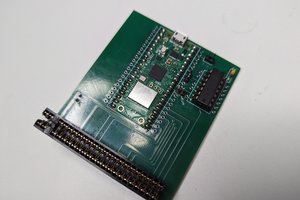
Here is PicoROM:
The Pico really does the work in this circuit. The rest of it is 74LVC245AN 8-bit logic level shifter chips, to safely interface the 3.3V Pico with my 5V Vectron 65 6502-based computer. For the 74LVC245AN attached to the data bus, I connect the chip's output enable pin to the Vectron 65's chip enable signal for the ROM. That sets the PicoROM data lines to high-Z for free, without taking any processing cycles.
Speaking of processing cycles... I have been using PicoROM with a 2 MHz system clock with perfect stability (the 6502 accesses memory in half a clock cycle, so it's really handling 4 MHz access times). I'm not sure how far it can be pushed, but it is handling my current requirement with no problems.
Media
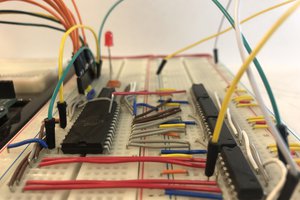
Running Vectron 65 OS with PicoROM: 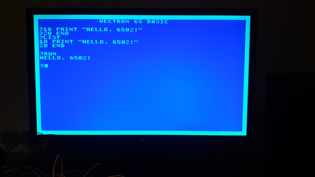
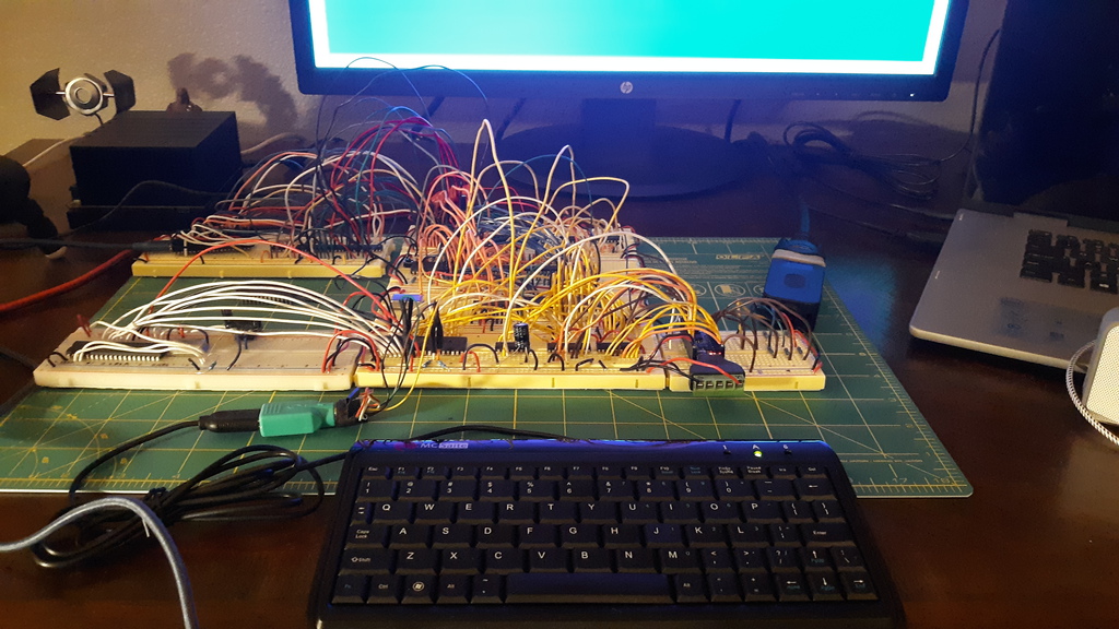
PicoROM attached to Vectron 65 (and ROM chip removed): 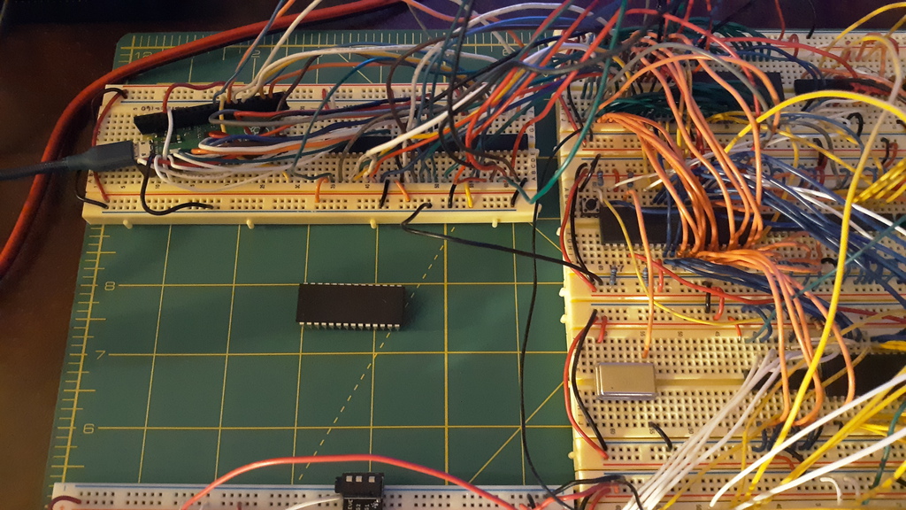
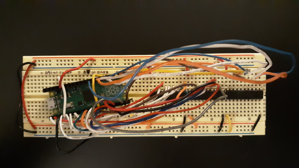
PicoROM close-up: 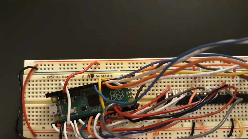
Bill of Materials
- 1 x Raspberry Pi Pico
- 3 x 74LVC245AN
About the Author
 Curtis Bucher
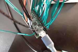
 David Robinson
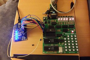
 Jac Goudsmit