 Albert Gonzalez
I wanted to build a small and compact Game of Life minidevice using an attiny85 and one of those popular small OLED displays (a 128x64 one in my case).
The idea was to build a somehow "portable" handheld Game of Life thing while learning more about the SSD1306 driver chip among the way, since my only previous experience with this screens was by using the Adafruit SSD1306 library on Arduinos and similar devices (and that's something you cannot use in the attiny85 - also, I'm not using the Arduino environment here!).
I thought it would be an "easy" project: I used some of my previous I2C bit banging code (a simple implementation I initially wrote for this NES Mini Controller USB Adapter) and started poking around with the available instructions and the datasheet configuration (also this post with some extra explanations regarding the SSD1306 modes and this SSD1306 C++ library for AVR micros) but then I realized something:
There wasn't enough space in the attiny85 SRAM to manage a dynamic full 128x64 buffer (with 1 pixel being 1 cell on the automaton)!
The main problem
For a 128x64 pixel grid, with each pixel being "on" or "off", I'll need 1024 bytes (128x64/8) of available space in the SRAM in order to dynamically populate the "cells" and, on each step, change them accordingly.
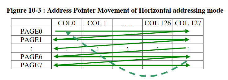
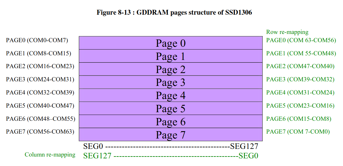 (all those images are from the SSD1306 datasheet)
But there are only 512 SRAM bytes on the attiny85! (and also I'm using a SECOND buffer in order to make the proper calculations per step and switching them when displaying, so that's even MORE space needed!).
Notice that if I used the flash memory itself to store some static data (like a single picture like the boot logo I made) I wouldn't have any problem (8k bytes of flash is enough for some cool photos!) but since I wanted to modify that grid this wasn't an option for me.
So I thought about shrinking the grid size. Or making the pixels bigger. It's kinda the same.
Bigger pixels, the solution
Instead of having a single 128x64 matrix, let's assume we have TWO different ones:
- The first one is the one from the display. A real 128x64 pixel grid that can be set by sending the proper commands and data via I2C. In my case I'm using the horizontal mode to send the different pages
- And the second one is an "internal" 32x16 grid and it's used only by the micro itself. It uses 64 bytes (32x16/8) and we have TWO of them (remember that we have TWO buffers to swap between iterations)
We handle all the "Game of Life logic" in a 32x16 matrix and update each buffer on each iteration and, when we need to send those buffers via I2C to the SSD1306 chip, we translate them so each one of our "internal pixels" is actually a package made of 4x4 "real pixels".
So, by dividing by 4 both width and height, we can manipulate up to 512 individual "big pixels"!
Sending the translated data
The SSD1306 works with pages and columns. Each page is, more or less, "an horizontal line with a thickness of 8 bits". A 128x64 display has 8 pages and 128 columns, and the way the info is sent to the screen depends on the mode (check the SSD1306 datasheet for more info about this!).
I'm using the horizontal mode, so that means I'm sending the pixels "from left to right". And since each page is "8 bits thick" that means I'm sending page after page until I reach the end.
And because I'm using an internal grid 4 times smaller than the "real one", those pages are actually "two bigger pixels thick" (instead of "8 small pixels").
With this in mind, I use the internal grid and:
- For each bit on the grid I build 4x4 equivalent pixels on a new structure for one page (that's basically putting all the bits one after the another in the proper format to be displayed as a "bigger square").
- Once I have a full 128 columns line (that's the full page) I send the proper commands to the SSD1306 and then send that single page to the driver (you don't need to send the whole buffer at once; actually you could send byte by byte instead of sending a big chunk of data - in my case each chunk is the full horizontal line)
- That new structure is flushed and re-used to build the next page ("the next 8 horizontal lines on the OLED screen").
- Once the 8 pages are completed, we're done!
And that's it! This is how we can manage a small 32x16 buffer and translate it into a 128x64 one!
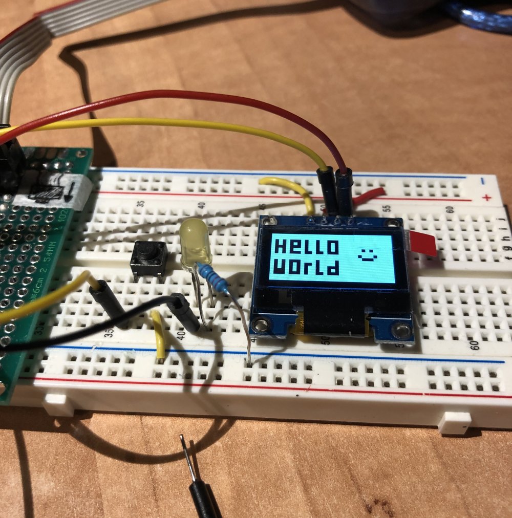 (test image using the "bigger grid")
Implementing the Game of Life
Once I had the grid system up and running, the game implementation itself was easy (I just needed to make sure I had enough space for TWO buffers - and 128 bytes for a couple of them was completely okay, so no problems here!).
The "playable area" is the 32x16 grid with each of the edges "looped" to the oposite one (so if you start walking to the right you'll end up appearing on the left side).
The game follows the "classic" rules, so on each iteration and for each cell:
- If it's alive and with < 2 neighbours the cell dies
- If it's alive and with > 3 neighbours the cell dies
- If it's alive and with 2 or 3 neighbours the cell lives
- If it's dead and with exactly 3 neighbours the cell lives
Each step iterates over a main buffer and writes the next state on a secondary one. After that, the buffers swap, the secondary becomes the main one and it's content it's displayed on the screen.
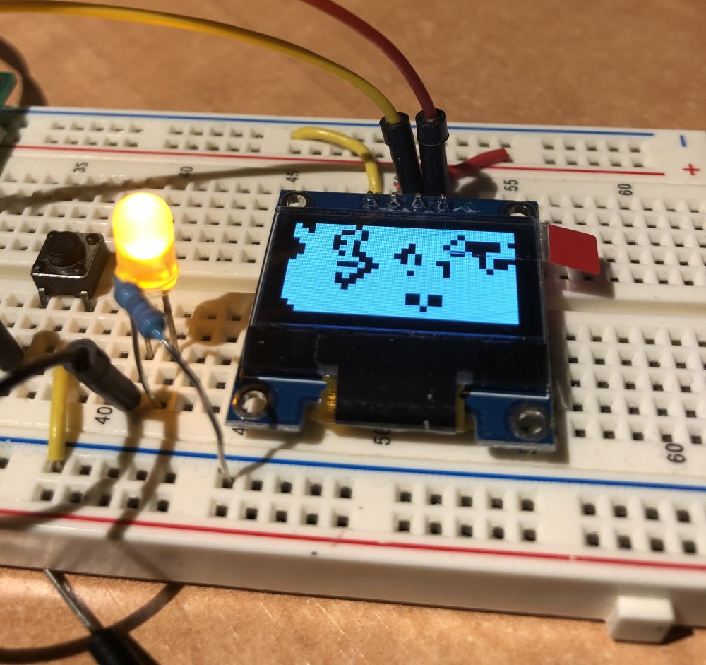 (automaton fully working on breadboard)
Speed
By clocking the micro at 16Mhz (without any external oscillator) the performance is acceptable. There's no need for extra delay between each of the steps, since the time it takes to calculate and send the data it's enough to keep the current image on the screen without being completely useless by a hyperspeed refreshing rate.
Features
- Classic Conway's Game of Life rules on a 32x16 "infinite" grid
- Custom made I2C bit banging handlers
- Custom made driver to handle a dynamic 32x16 buffer (set_pixel / get_pixel / send_buffer and all that stuff)
- Commands and data to the SSD1306 chip can be send in multiple ways (from flash memory, one byte at a time, on a multiple bytes package...)
- Boot logo / splash image stored on flash memory
- Start / reset button to start a new "game"
- Dead-end autodetection: if there're no changes between steps the game performs a reset and starts again (this can be done by checking each of the cells and making sure there's, at least, ONE change between the previous and the next buffer)
- Pseudo-randomness based on the delay between button pushes (not the most effective and secure method, I know, but for generating simple seeds it works pretty nice! :D)
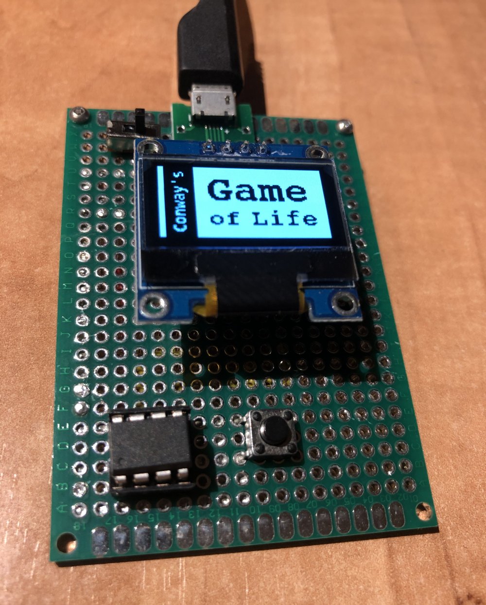 (final version - check out the boot logo image! :D - on protoboard)
Problems, bugs, things to solve, limitations...
- Maybe the grid handling could be improved to be faster
- The dead-end detection cannot detect a scenario with the automaton iterating between two different states (since there's at least one change on each turn this is, technically, a not a dead-end; so to be able to discard "repetitive patterns" we'll need to store previous buffers, and that's something I didn't wrote - and having the reset button I think I won't)
Hardware
I initially built it on a breadboard and thought about making a small enclosure (like a handheld device or something like that), but I ended up with this protoboard with a couple of 3D-printed supports and a USB port for power only.
I'm planing to have it next to my keyboard at work and use it as a real-life distracting widget while commiting code or waiting for deploys to finish.
Things I've learned
- Working with the attiny85 limitations
- Memory management (SRAM and flash)
- How the SSD1306 works
- It's always fun to implement a Game of Life! : D (well, that's not actually anywhing new...)
See it in action!
I've uploaded a couple of videos to my twitter account, here and here!
Source code
Links and extra info
- SSD1306 datasheet
- Debugging SSD1306 display problems, probably the best post about the SSD1306 datasheet I've found
- SSD1306-AVR, a C++ library for the SSD1306 chip. I initially found this one and started porting it into C, then I realized the buffer issue with the attiny85 and use it as a reference while developing my own driver (I use the same constant command names than the ones listed in the constants file, btw)
- image2cpp, one of those "load a BMP and format it into a bunch of bytes ready to be sent" pages. I used this one for the boot logo conversion