CONTROL UNIT DESCRIPTION
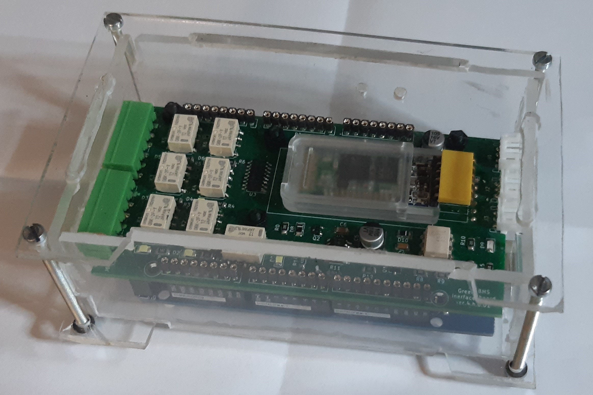
Control Unit is the BMS main unit, it is based on Opensource Microcontroller Arduino Mega. Control Unit functions are:
- Communicating by I2c with all the cell modules of the battery pack
- To receive from cell modules the values of: cell voltage, cell pole temperature, balancing resistor temperature for battery pack management system
- Sending to cell modules the balancing command
- To perform the following safety functions by relays:
- Charge ok: open two relays contact when just one cell of the pack reach the high value or I2C communication with Cell modules is loss
- Discharge ok: open a relay contact when just one cell of the pack goes down the minimum value or I2C communication with Cell modules is loss
- Alarm led: close a contact to supply a led in case of alarm
- Balancing: close a contact when just one cell of the pack is balancing: Green BMS System uses this signal to reduce the charging current (see Green BMS Limiter)
- System OK: closes the contact when the Control Unit has to switch off to avoid unnecessary consumption. Green BMS System uses this signal to drive an external power stop circuit to the Control Unit.
- To communicate with an Android device by a Bluetooth module. (see Green BMS Android app)
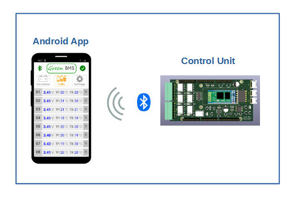
Through the android application it is possible to perform the BMS calibrations: System stores all the parameters in the Eeprom memory of the Arduino Mega Microcontroller inside Control Unit.
CONTROL UNIT HARDWARE
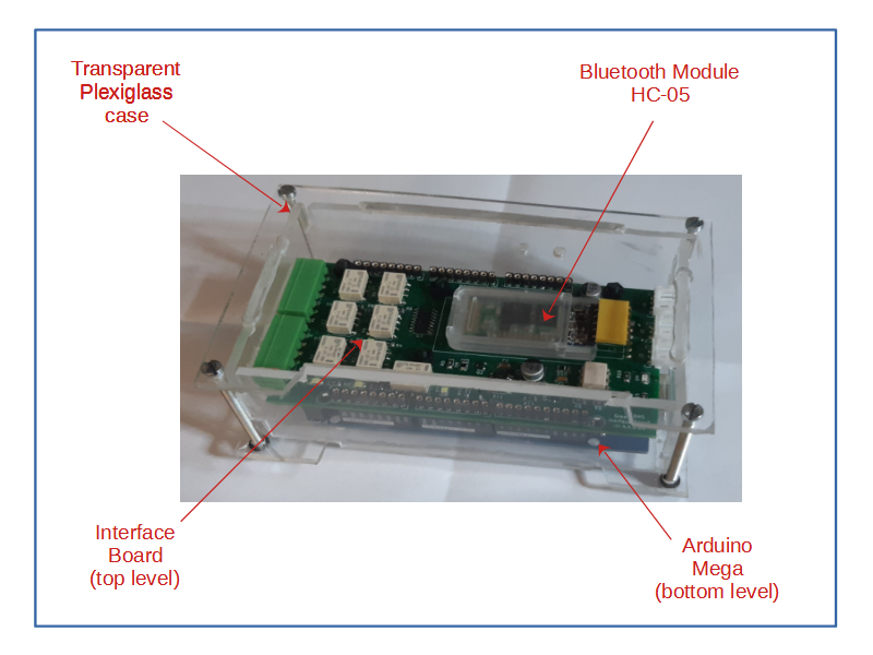
The picture above shows the main components of the Control Unit. Arduino Mega is the backplane of Control Unit, it must supplied at 12vdc by the relevant connector.
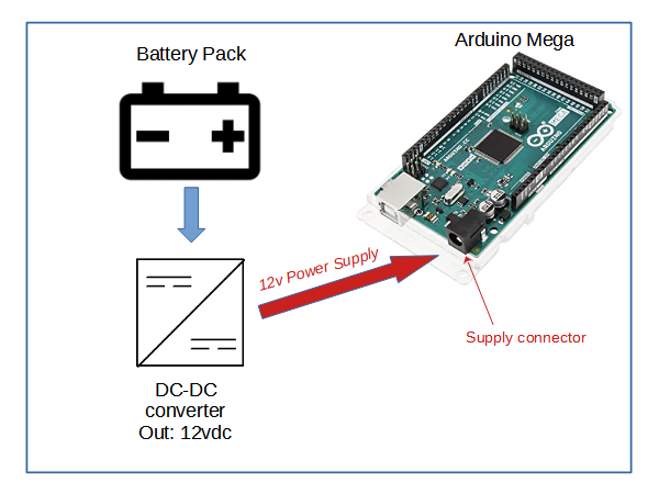
To supply Arduino Mega and all the Control Unit functions, You must use a DC-DC converter to convert the total battery pack to 12vdc.
Arduino Mega is a commercially available Opensource card.
The Interface board is inserted above the Arduino Mega.
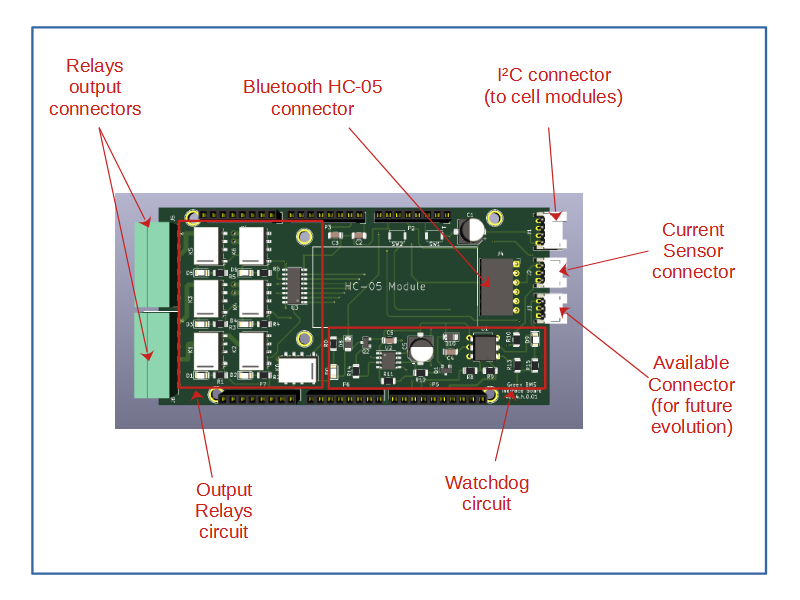
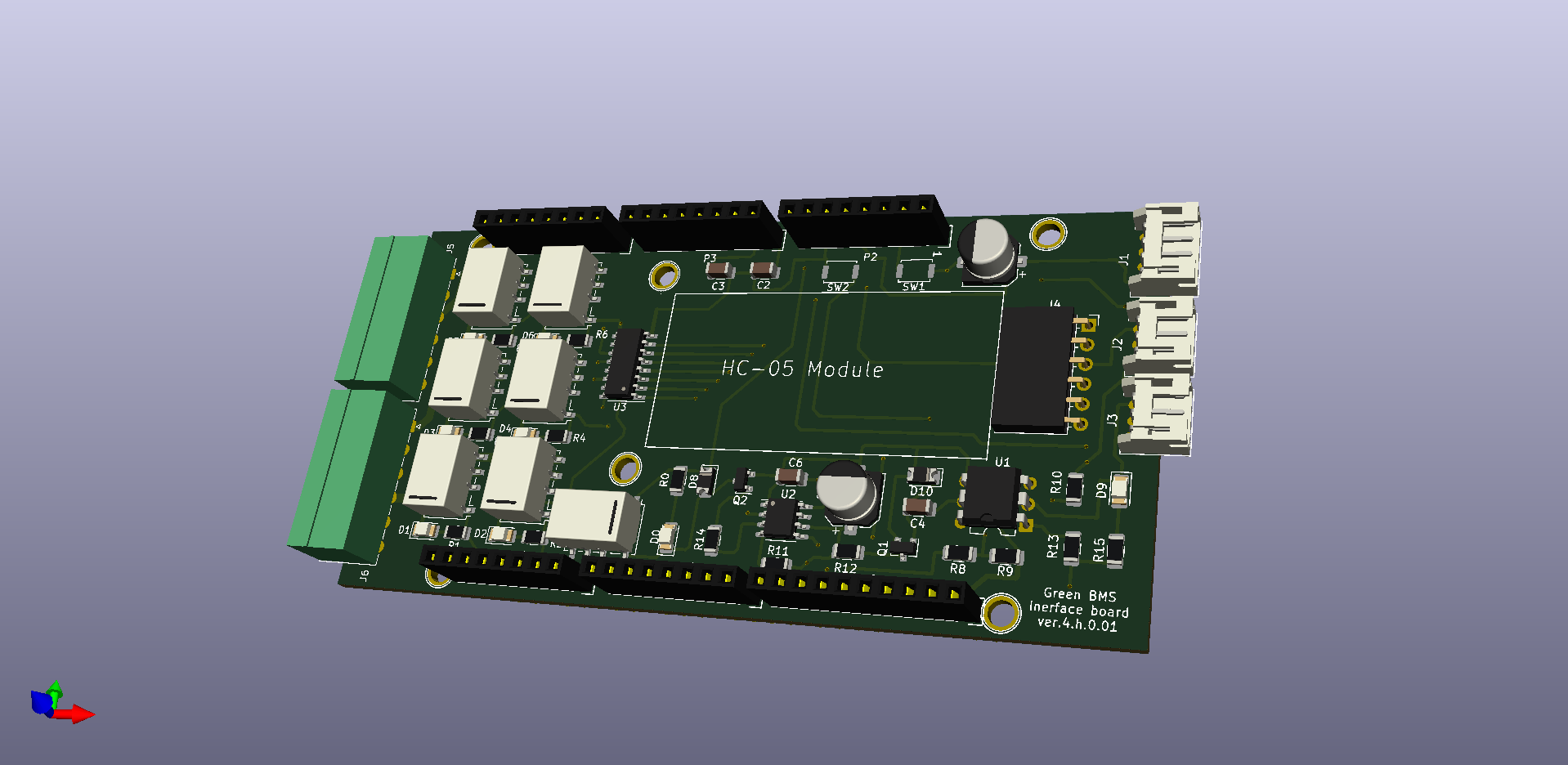
The interface board includes the control unit input / output connectors. The interface board includes a watchdog circuit that de-energizes the relays in the event of a software crash. The mini output relays (12vdc coil) are driven by a driver IC.
IMPORTANT: the maximum current supported by the relay contacts is 1A, do not use these contacts directly in the battery charge-discharge circuits, but use them to drive power relays!
The control unit has an average consumption of 5.5 watts. If you always leave it powered, even when it is not needed, it can discharge the battery pack in a few days! For this reason it is absolutely necessary that the 12v power supply circuit be designed so as to switch off the Control Unit when the discharge or charge operations are not active. In any case, it is advisable to keep the battery pack charged after each discharge and in case of prolonged periods of inactivity of the battery, provide for a weekly charge.
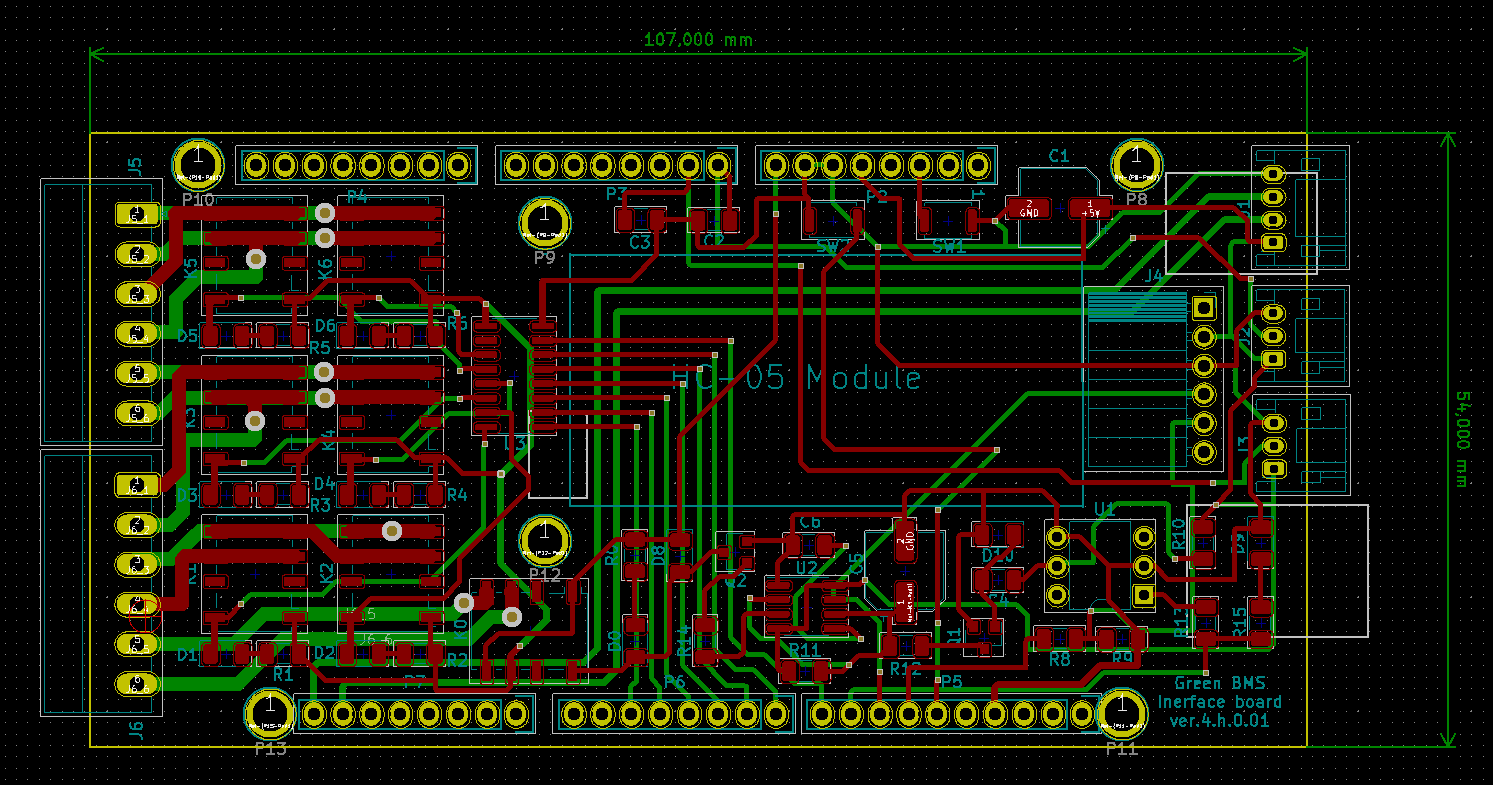
Interface Board PCB was designed with Kicad Opensource application.

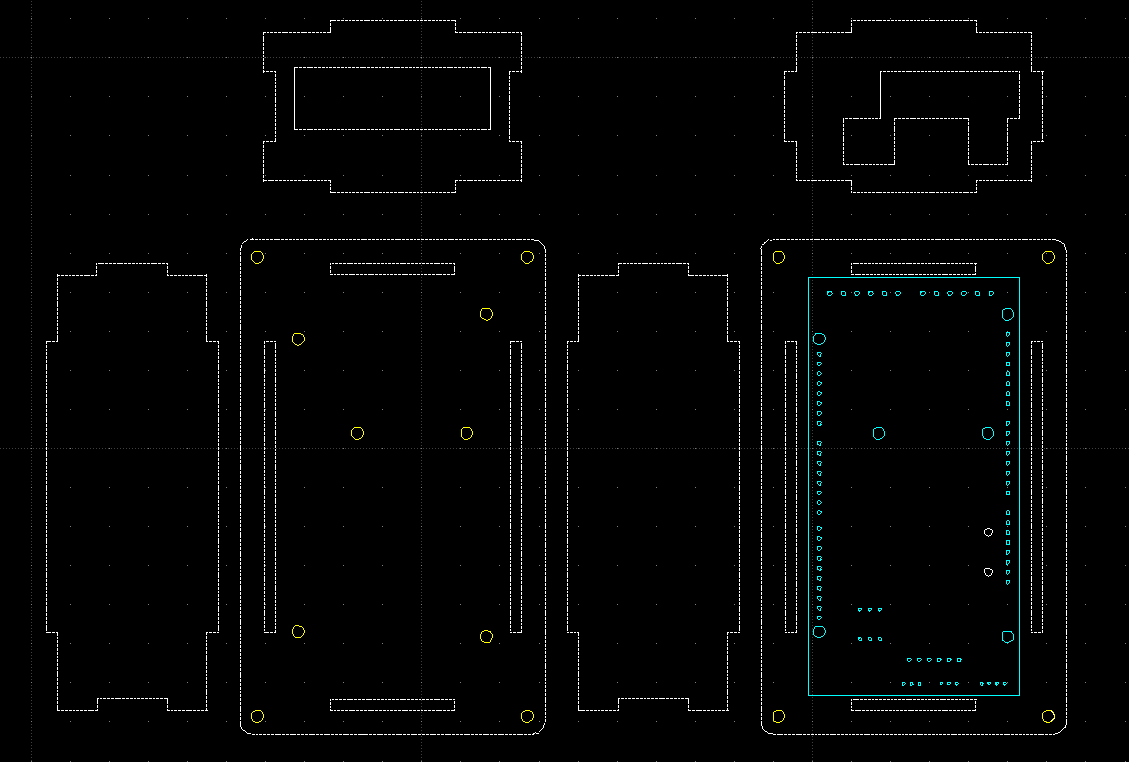
Control Unit transparent plexiglass Case cut-out drawing, was designed with Opensource 2D cad Librecad.

All project files are available in the Github repository
CONTROL UNIT SOFTWARE
The software present in the Arduino Mega was developed using the Opensource Arduino IDE application
The software is loaded using a standard USB cable (generally provided with Arduino Mega), connected on the relevant port.
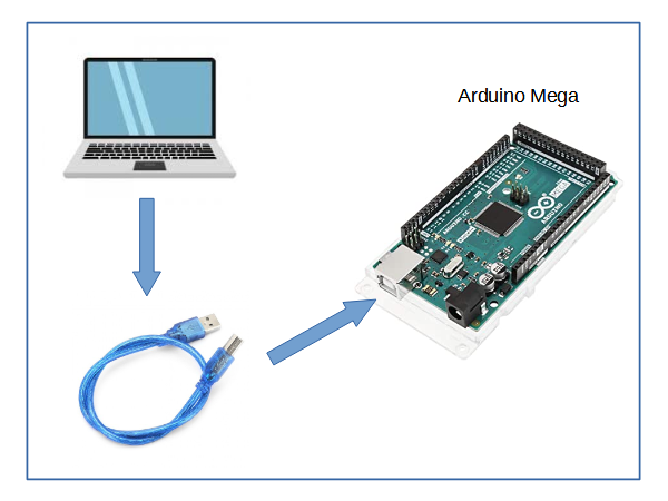
You can download it in the Github repository.
 Sergio Ghirardelli
Discussions
Become a Hackaday.io Member
Create an account to leave a comment. Already have an account? Log In.