Using the "Green BMS" Android app it is possible to connect to the BMS Control Unit to have a complete diagnostics on the system status and to be able to configure the battery pack and the behavior of the BMS according to your needs.
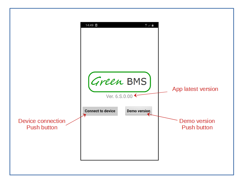
Upon opening, the application displays the following page:
By pressing the "Demo version" button, you can test the application offline to discover its functions.
Pressing the "connect to device" button, the smartphone screen shows all the available bluetooth connections. Select the one related to the HC-05 module. When the connection is active, the Login window appears.
To be able to connect to the device it is necessary to enter the 4-digit numeric password, which upon first use is "1234".
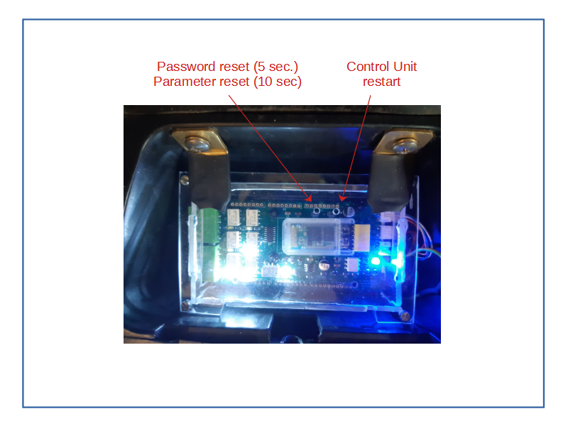
It is possible to change the password in the "settings" page. The password remains stored in the Eeprom of the Control Unit. In case of forgetfulness, the system offers the possibility to do a "password reset" by pressing the "SW2" button on the Local Control Unit for 5 seconds.
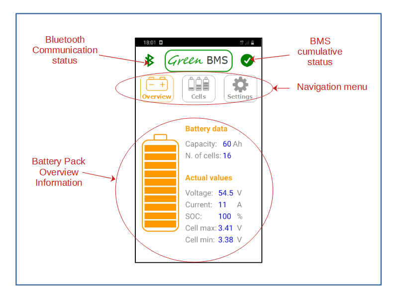
In case of successful login, the display shows the "Overview" page:
The top part is common to all 3 pages that make up the system and shows the status of the Bluetooth communication (green = OK red = communication lost) and of the BMS system (green = no alarm red = just one alarm).
In the lower part of the page the animated values related to the battery pack are shown:
Capacity (Ah) according to user settings
Number of cells in series, according to user settings
Total voltage (V)
Current (A) = actual current measured by current sensor, Positive value is for charging current, Negative value is for discharging current.
SOC (%) = state of charge in percentage calculated to capacity setting
Cell max (V) = Highest cell voltage value
Cell min (V) = Lowest cell voltage value
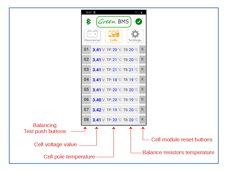
Pressing the "cells" button, a page appears showing the data of each single cell.
By scrolling the page, all the cells of the pack set by the user are displayed.
For each cell, the following read-only data is displayed:
Voltage (V) = text in blue color is for voltage in normal range, orange color means that the cell is balancing, red is for voltage over Very high voltage threshold or under Low voltage threshold
Cell pole temperature (°C) = it shows the temperature measured by the sensor attached to the cell pole. Blue text is for temperature in normal range, red is for value over the High temperature setting
Cell pole temperature (°C) = it shows the temperature measured by the sensor attached to the cell pole. Blue text is for temperature in normal range, red is for value over the High temperature setting
Balance resistors temperature (°C) = it shows the temperature measured by the sensor attached to the balance resistors. Blue text is for temperature in normal range, red is for value over the High temperature setting
Cell module communication fault = this event is shown by the red animation of reset button
For each cell, the following functions are available:
Balancing test push button = pressing it you can check the balancing circuit of each madule. This test is also important to verify the correct cell module address
Cell module reset button = pressing it you can reset the cell module
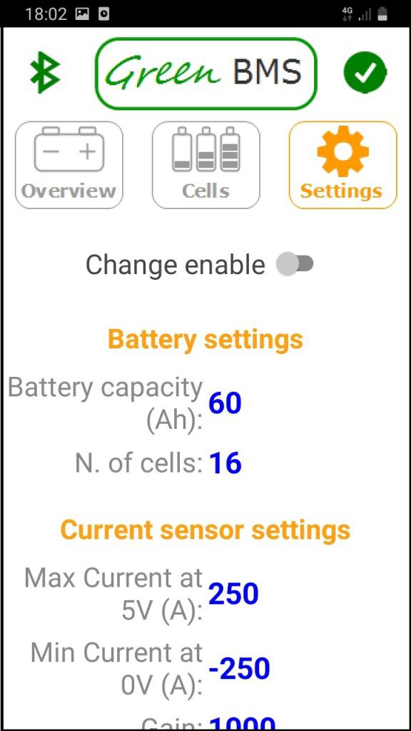
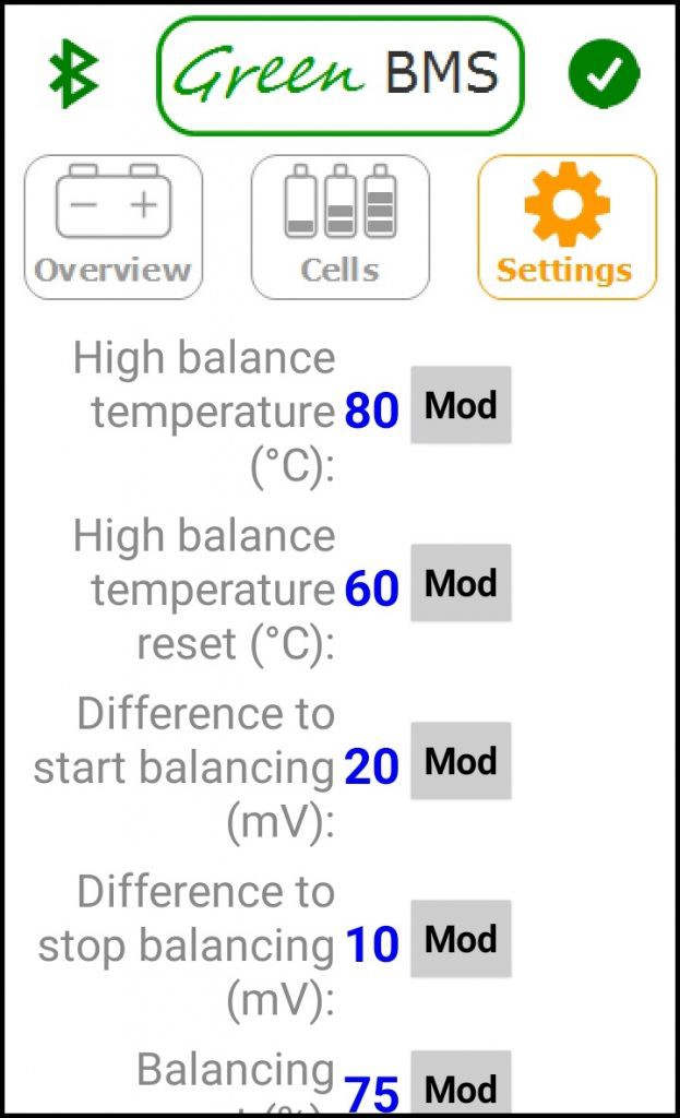
Clicking on settings the following page appears:
The "Settings" screen shows all the parameters loaded into the Control Unit memory and modifiable by the User.
When using the BMS for the first time, or in case of "Parameter reset" (SW2 for 10 sec.), the system loads the default parameters relating to a Lifepo4 48V pack.
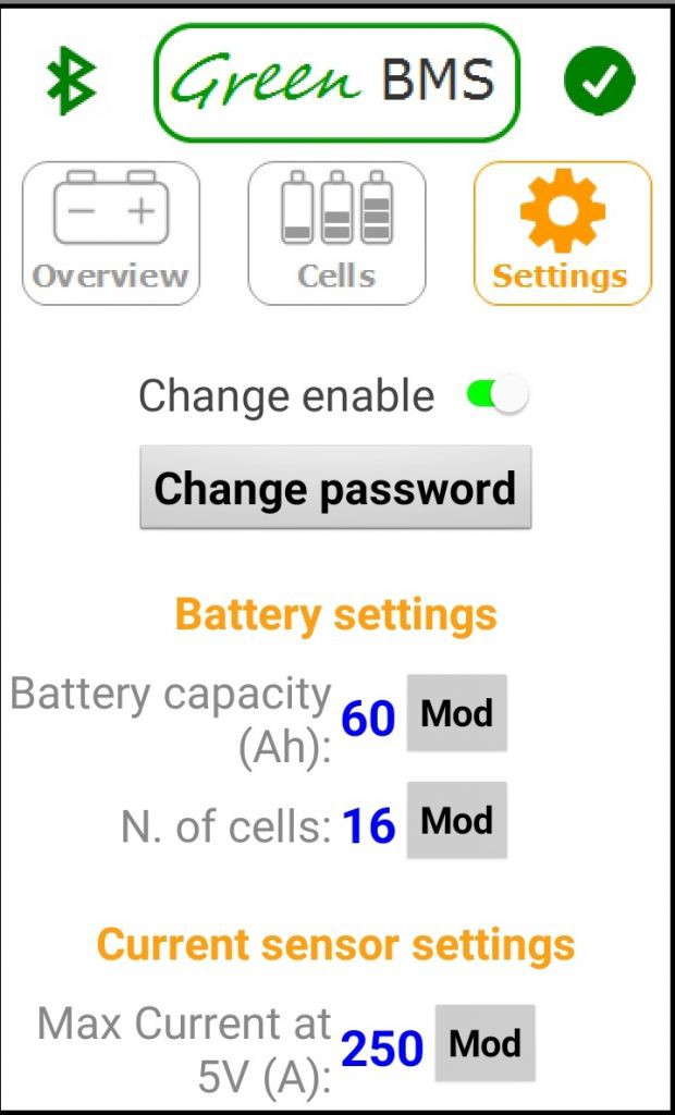
By clicking on the "Change enable" switch it is possible to modify all the parameters adapting them to your battery pack.
To modify a parameter, click on the "Mod" button alongside and type in the desired value.
Here is a summary of all the parameters:
BATTERY SETTINGS:
Battery capacity (Ah) = Total capacity of the battery pack used for SOC calculation
N. of cells = The number of the cells (in series) that compose the battery pack. This choice automatically affects the number of cells displayed in the "Cells" page!
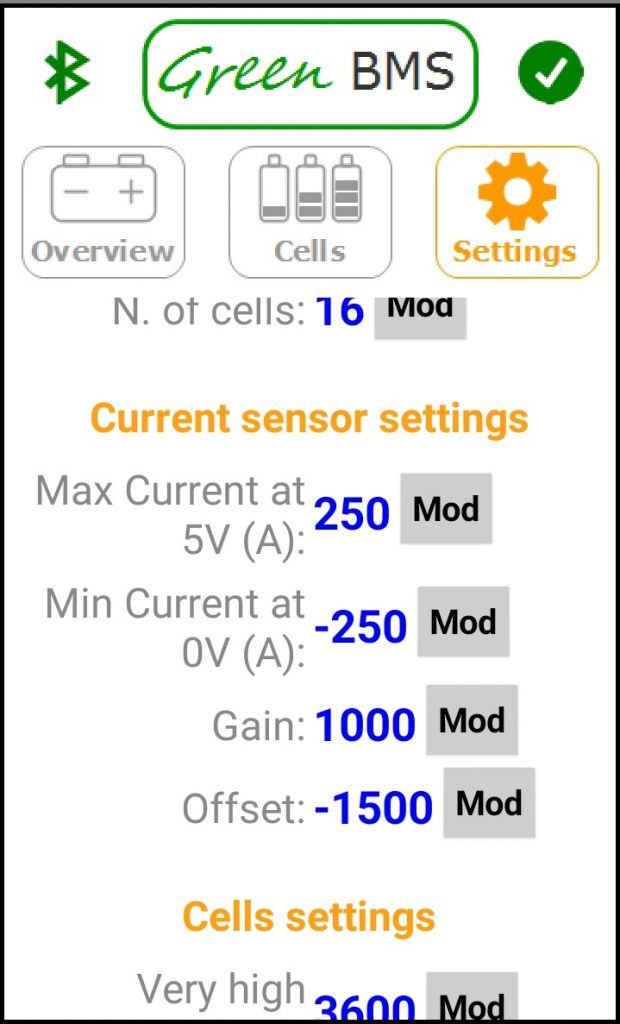
CURRENT SENSOR SETTINGS:
Max Current at 5V (A) = Maximum current value corresponding to the 5v output from the sensor.
Min Current at 0V (A) = Minimum current value corresponding to the 0v output from the sensor
Gain = Gain compensation value (1000 = gain 1)
Offset (mA) = Offset compensation value
CELLS SETTINGS:
Each state that is activated on the basis of a threshold, both increasing and decreasing, is managed and parameterized according to the graph below
Very High Voltage (mV) = very high voltage threshold, which causes alarm
Very High Voltage reset (mV) = reset threshold (falling) of the very high voltage alarm.
High Voltage (mV) = high voltage threshold, which causes the stop of charging if one of the cells reaches this threshold.
High Voltage reset (mV) = reset threshold (falling) of the high voltage alarm
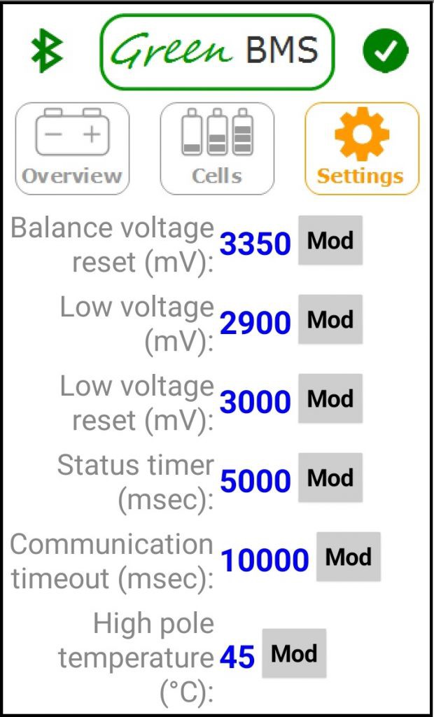
Balance Voltage (mV) = When a cell reaches this threshold, in the event of an unbalanced pack (see "difference to start balancing" parameter), the cell starts to balance.. When all the cells reach this threshold, the battery pack is considered charged and the charge is stopped.
Balance Voltage reset (mV) = reset threshold (falling) of the high voltage alarm
Low voltage (mV) = Low voltage threshold, which causes alarm and opening of the discharge consent relay
Low voltage reset (mV) = reset threshold (rising) of the Low voltage alarm
Status Timer (msec) = State activation time (valid for all states)
Communication Timeout (msec) = Communication error time with the cell, after which a "communication error" is generated and a reset command is sent to the cell module
High Pole temperature (°C) = high temperature threshold detected by the sensor placed on the cell pole. In addition to generating the relative alarm, this condition causes the opening of the charge and discharge consent relays
High Pole temperature reset (°C) = reset threshold (falling) of the High Pole temperature alarm
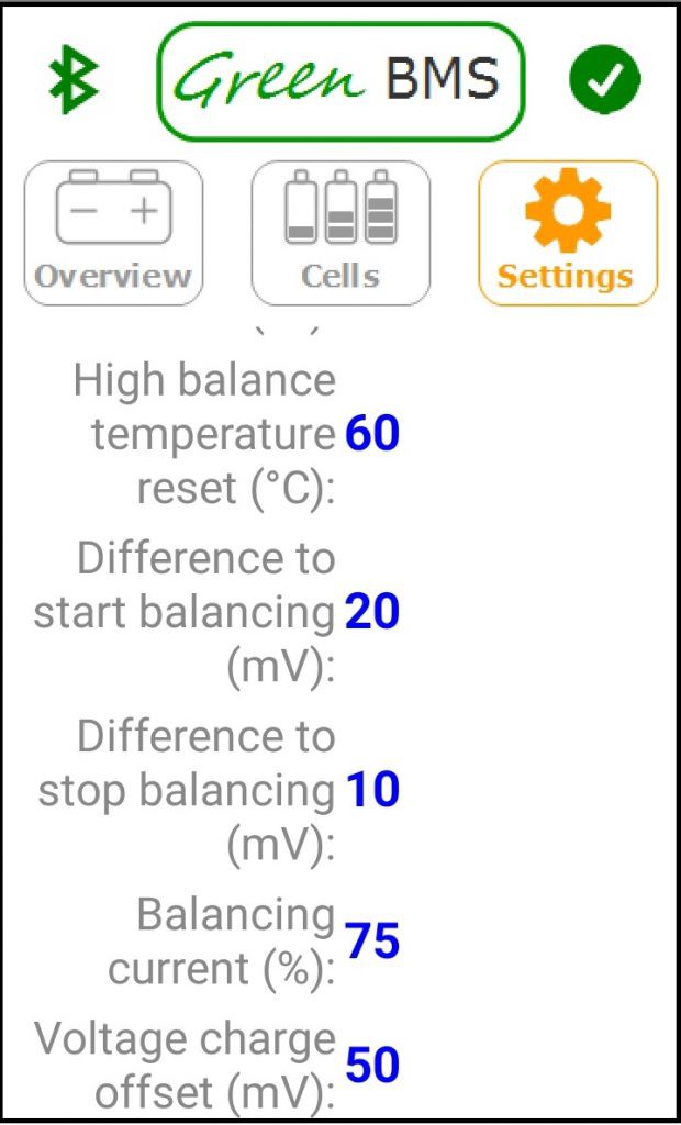
High Balance temperature (°C) = high temperature threshold detected by the sensor placed on the balancing resistors. In addition to generating the relative alarm, this condition causes the cell balancing to stop
High Balance temperature reset (°C) = reset threshold (falling) of the High Balance temperature alarm
Difference to start balancing (mV) = It is the parameter that determines the cell balance, in this way: when a cell reaches the "balance" status, if the difference between its voltage value and the lowest voltage value of the pack exceeds this threshold, the cell starts to balance
Difference to stop balancing (mV) = during cell balancing, if the difference between its voltage value and the lowest voltage value of the pack is less than this threshold, the cell stops to balance
Balancing current (%) = It is the parameter with which the balancing currentis set, which depends on the balancing resistance. For example: if you decide to balance at 3400 mV and the balance resistance is 3 Ohm, the maximum balance current corresponds more or less to 1 A. If you set this parameter to 100% you decide to balance at 1 A, at the 75% will be 0.75A, at 50% 0.5A...
Voltage charge offset (mV) = This parameter was introduced to compensate for the voltage difference of the cells during charging, with respect to their no-load value. This offset is very useful if the Limiter is used, because it avoids the continuous alternation of start and stop balancing due to the aforementioned voltage differences.
It is possible to download the application for free from the Google Play store:
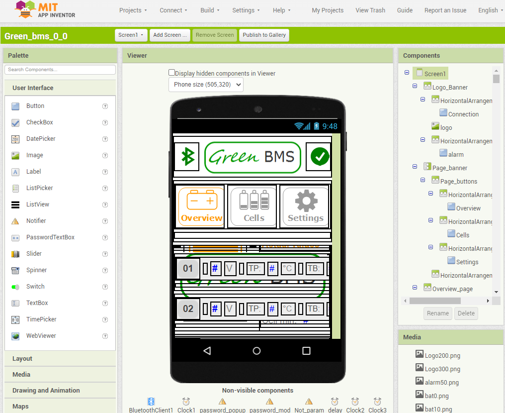
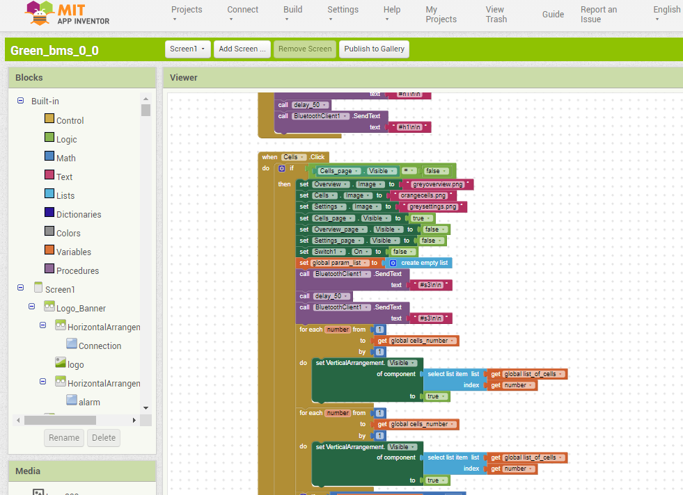
DEVELOPMENT TOOL
The application was created using the online opensource development tool: "Mit App Inventor"
 Sergio Ghirardelli


Discussions
Become a Hackaday.io Member
Create an account to leave a comment. Already have an account? Log In.