 Sergio Ghirardelli
Attiny84 microcontroller consents to measure the supply voltage, avoiding the use of an analog pin.
How is accurate this measurement?
In this phase of the design I made a bad discovery: connecting several controllers to the same power supply, I had different measurements, with values that differed even by 30-40 mV!
Panic…
In order to solve a situation like this, experience teaches me that we need to calmly collect the necessary data ...
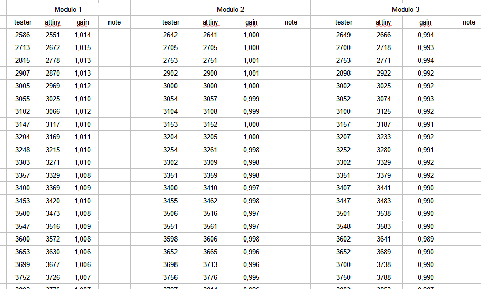
So I connected 3 different attiny microcontrollers (one at a time) to my bench linear power supply, and I collected in an excel sheet the voltage measured with my multimeter and that detected by the microcontroller, for a scale from 2.6v to 5v, taking a measurement every 50 mV
I first tried to figure out if there was simply an offset to add up to compensate for the error, but I quickly saw that this was not constant.
So I created a calculation column where I reported the gain, according to the formula:
gain = V_measured (multimeter) / V_attiny (microcontroller input)
After which I reported the gains of the three modules in a graph as a function of the measured voltage, with the aim of finding a visual relationship between the gains of each module.
This is the resulting graph:
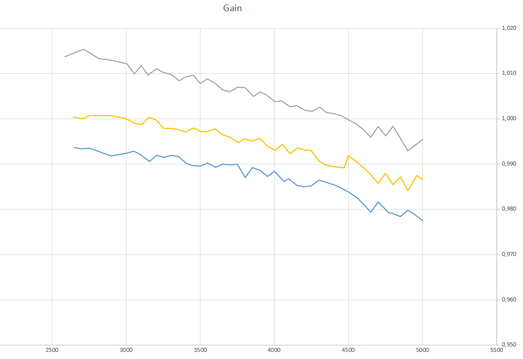
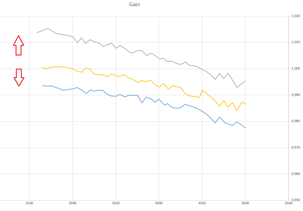
Looking at the trends, we see that the gain drops with increasing voltage, with a similar range, for all the modules. The difference seemed to be just a question of offset:
So, playing with the data, adding or subtracting an offset, I was able to superimpose the trends of the 3 gains:
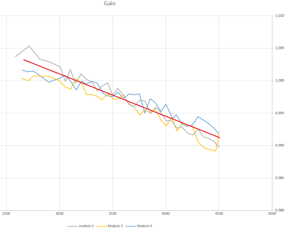
So, summarizing, I found that:
- for each module, the gain varies linearly as a function of the voltage following the same angular coefficient
- In order to accurately calibrate the voltage, the user must be able to set the offset of each module…
At this point the question was: how?
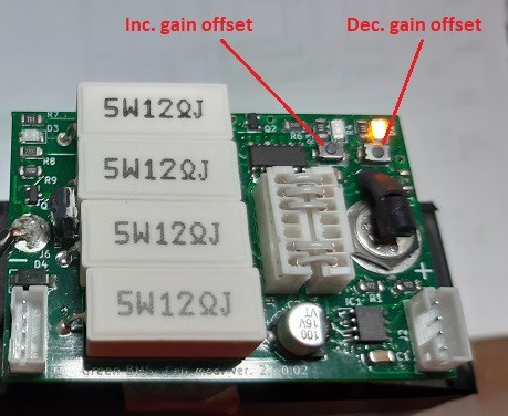
The simplest and most immediate way to perform this “one time” setting was to increase and decrease the offset using the buttons on each module, storing the Offset value on the eeprom …
The result was satisfactory !!!
I have done several tests on 16 cell modules, varying the voltage and the measurement has never shown an error greater than 10 mV!
In the following video I show how to perform this calibration:
Discussions
Become a Hackaday.io Member
Create an account to leave a comment. Already have an account? Log In.