 Chris Combs
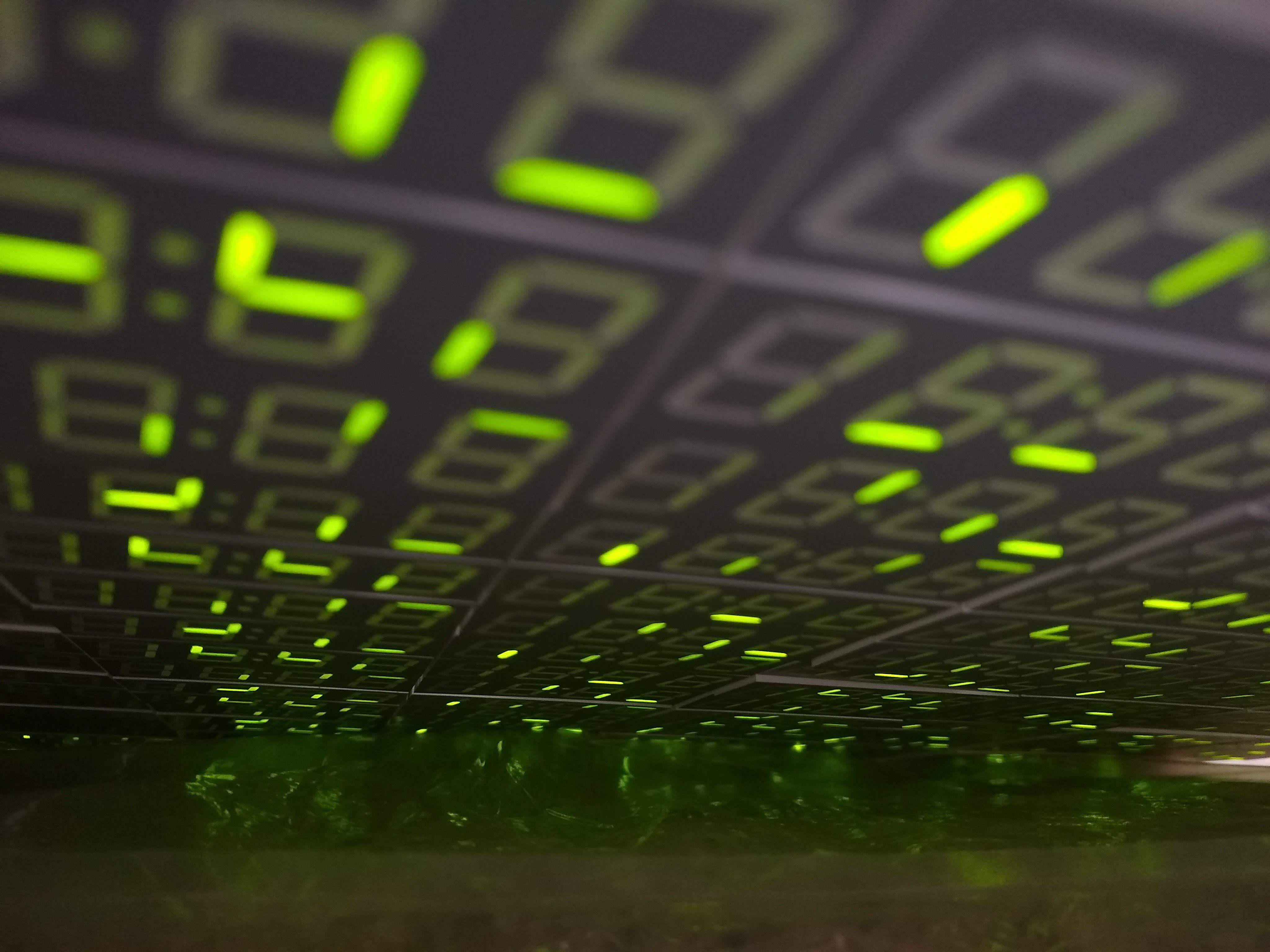
(First light)
I really like the IS31FL3733 i2c matrix controllers I'm using in this project, but they do have one limit that I ran into fairly quickly. You can only have 16 of them on one i2c bus. Due to the large numbers of displays in this project, I needed to use 48 of them.
It's possible to use a multiplexer to fit more devices on to a single bus. But there are other problems with so many devices on a single bus: bus capacitance begins to be a problem (can each device quickly overcome the increasing capacitance to drive the bus to ground in a timely manner? this takes more and more current), as does having enough bandwidth to update all of the displays at a reasonable framerate.
I began to wonder about using multiple i2c buses. The Raspberry Pi 4 has device tree overlays that enable something like 6 buses total. I had used one extra bus in a recent project ("Madness Method"), but only in a low-bandwidth way; could I keep three buses constantly busy updating these displays?
I tried it out, enabling i2c3 and i2c4. This is done through adding extra dtoverlay lines to /boot/config.txt, following the templates here:
https://raw.githubusercontent.com/raspberrypi/firmware/master/boot/overlays/README
In my case, I chose pins_4_5 for i2c3 and pins_6_7 for i2c4; having all the pins near each other made the board routing cleaner.
dtparam=i2c_arm=on,i2c_arm_baudrate=800000

dtoverlay=i2c3,pin_4_5,baudrate=800000

dtoverlay=i2c4,pin_5_6,baudrate=800000
After the device tree overlays are set up, restarting the Pi causes /dev/i2c? entries to appear. The numbers matched up for me, though I've read others reporting that the bus numbers might not exactly match but were in the right order (example: i2c5 and 6 showing up as buses i2c3 and 4)
A side note for i2c4 pins_6_7: Pin 7 can also be CE1 for the SPI0 bus. If you have a library, like RF24, that uses the bcm2835 library to initialize the SPI bus, it will grab 7 for CE1, even if you are using CE0. This led to timeouts on the i2c4 bus in my case.
Between the extra bus connections and my desire to add power conditioning (PTC fuse, capacitors, TVS+zener diodes) I realized I needed a support boars ("warm bath") for the Pi 4. Luckily, I had just designed a similar board for another recent project ("Subset"). I used this "camera host" board as the base and added connectors and supporting circuitry for i2c3 and i2c4.
One intricacy of using the IS31FL3733 is that it, mercifully, doesn't require any sort of external transistor or driver to handle typical LED matrices. But it needs a little headroom to switch, almost half a volt: 150mV on the current source side, 300mV on the current switch side.
It accepts a wide range of input voltages: 2.7-5.5V. If I were to power this chip with 3v3, I wouldn't be able to switch a 3.2V white LED. So I generally power these controllers with 5V. Even when the LEDs I'm using aren't white or blue, I like to have a little headroom, and using a higher voltage lets me pull a given wattage at a lower current, lowering heat build-up in my wires and boards.
The Pi uses 3v3 signaling, so it can't always communicate with a 5v i2c device reliably. On my "warm bath" board, I placed three assembly-configurable PCA9306 level converters (and, crucially, pull-ups) to bring the Pi's i2c levels up to 5v. The PCA9306 devices can perform up to 100MHz (not a typo), but anything more than a MHz takes some fairly dramatic pull-ups; in this project I ended up with around 523 ohms (1k on the board, 2k2 at two points at bus endpoints).
Once I had the host board ready to go, with three i2c buses, it was time to wire it up to the panels and start working out the power arrangements. More on this in my next update.
Discussions
Become a Hackaday.io Member
Create an account to leave a comment. Already have an account? Log In.