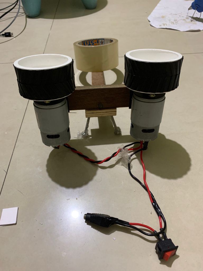
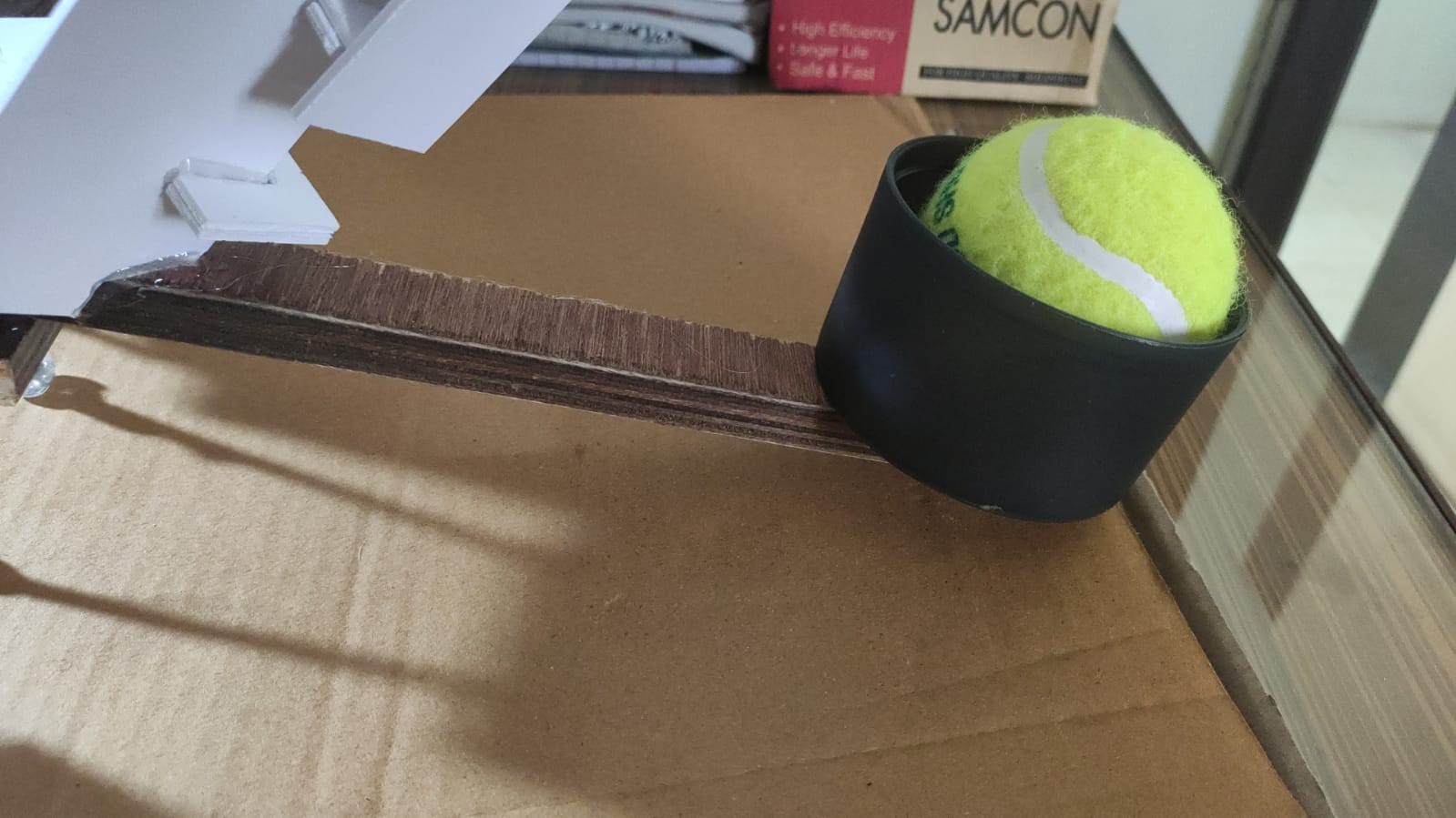
This Ball Thrower Bot was highly inspired by Baseball pitching machines and Cricket ball Bowling machines. It uses a flywheel assembly to throw the ball out of the contraption.
The Ball Thrower Bot test videos can be viewed here. Overall, I have a very satisfied puppy. She loved the build, though she still needs to learn how to use it properly. Since that is a lengthy process and is not very relevant, I will not be including that here.


 dearuserhron
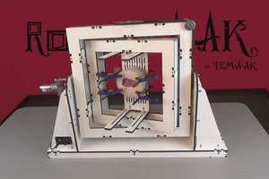
 Johan R. Botha
 John Leeman
 Andy
Andy