 Maximiliano Palay
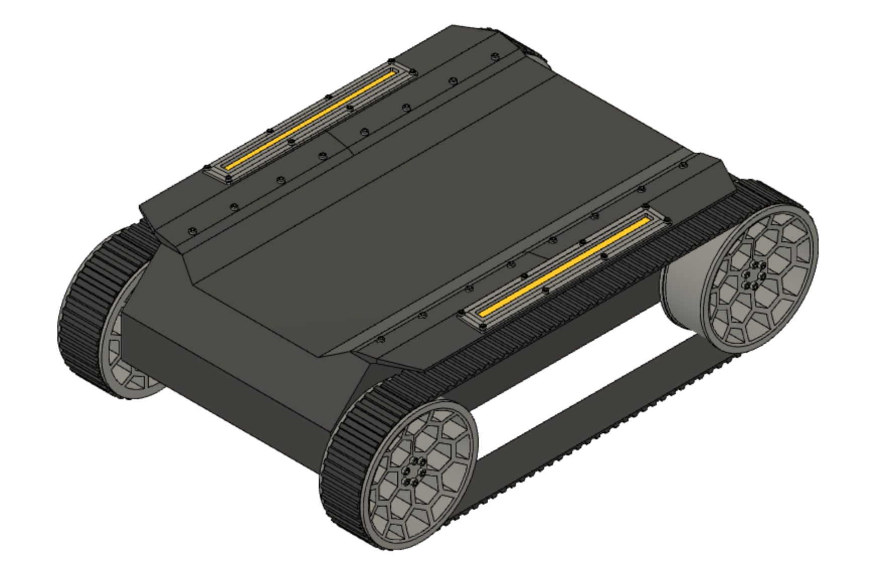
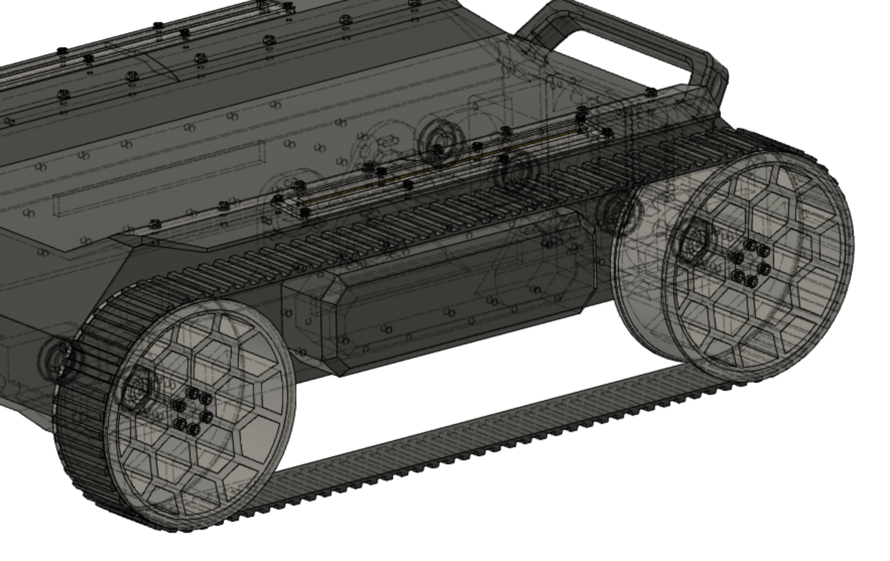
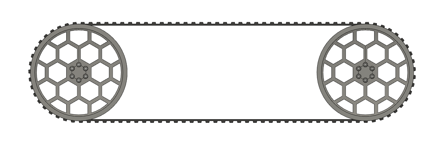
To make this project I took inspiration from other robotics platforms. The most known type of vehicle that use tracks are tanks, so why not get some inspiration from them too? Didn't want something too military-looking, though.
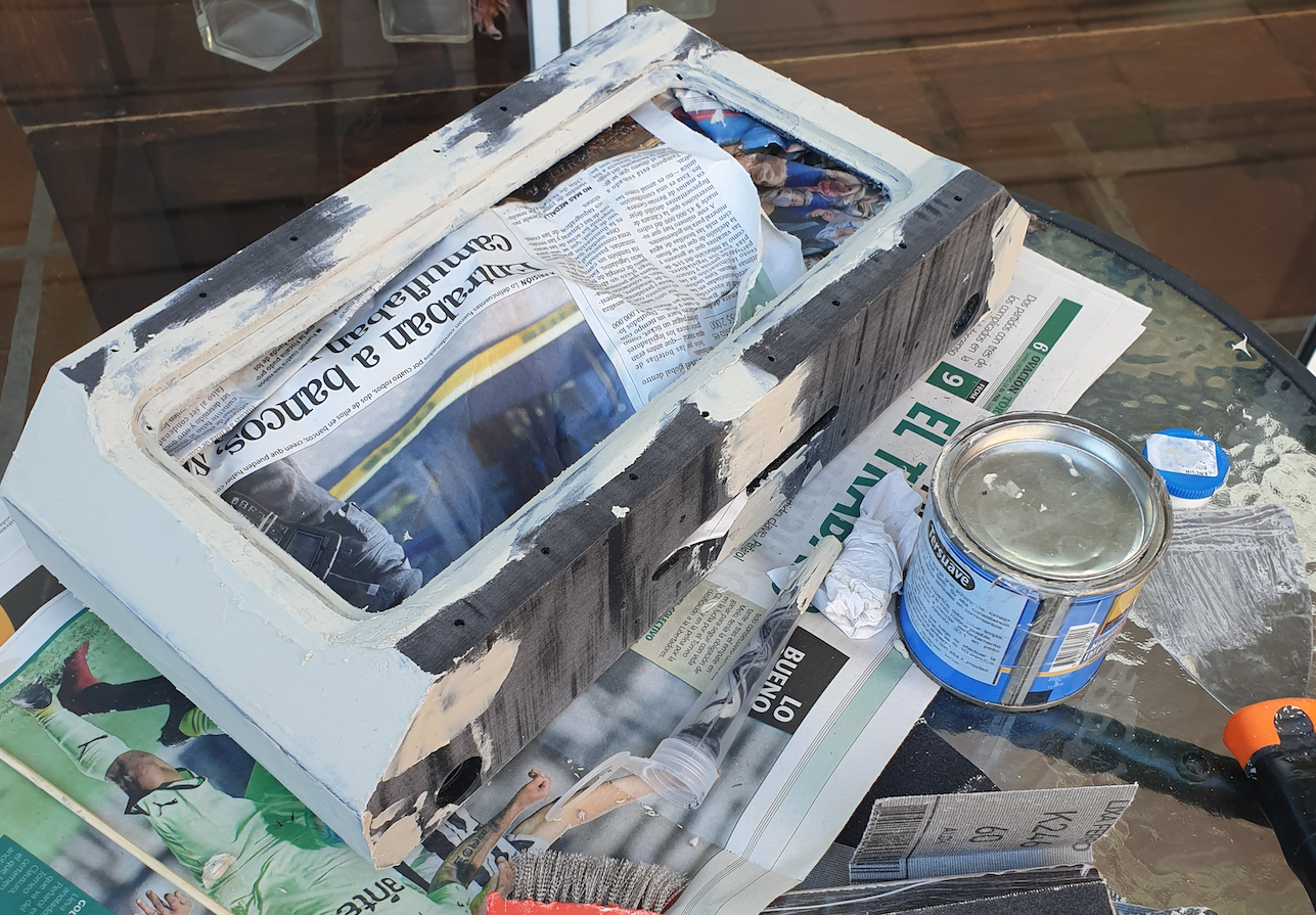
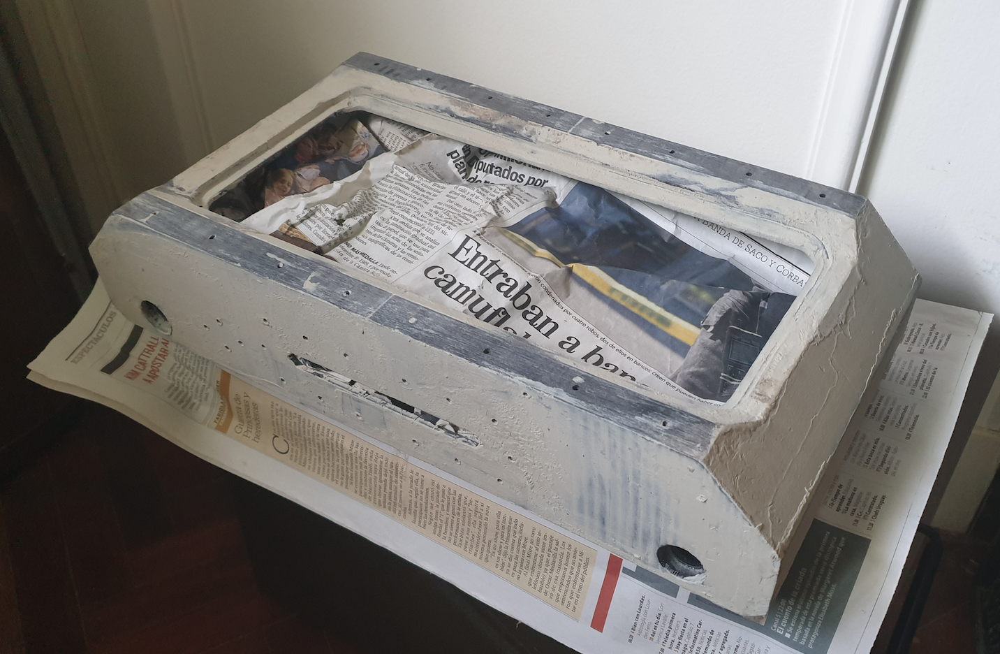
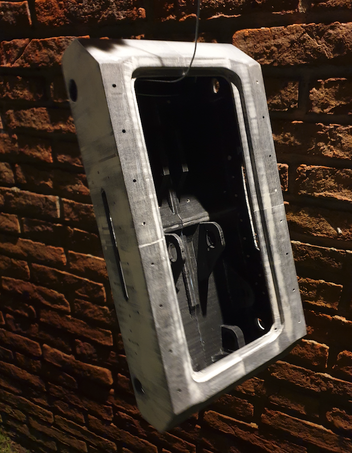
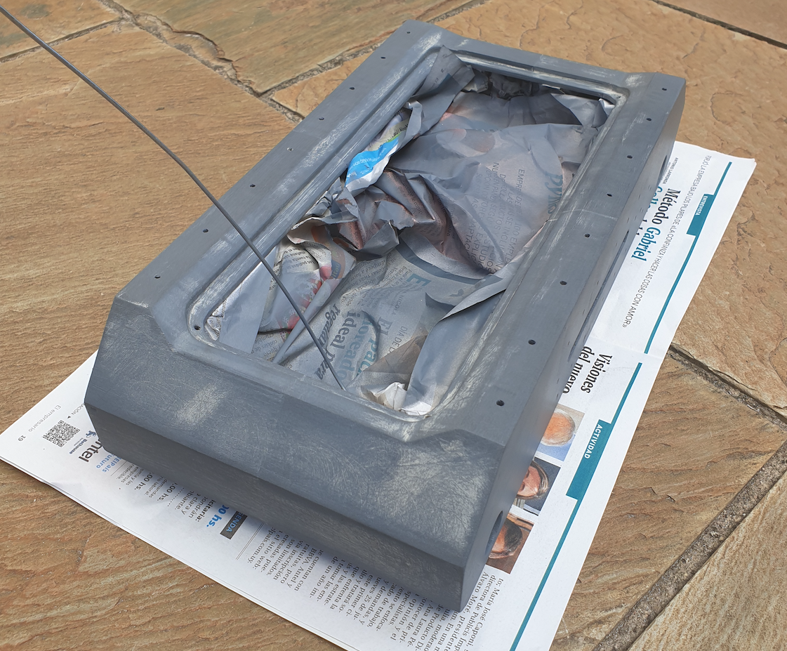
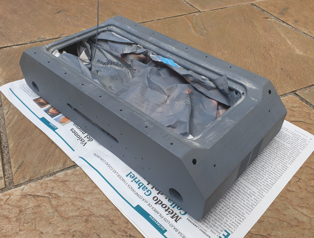
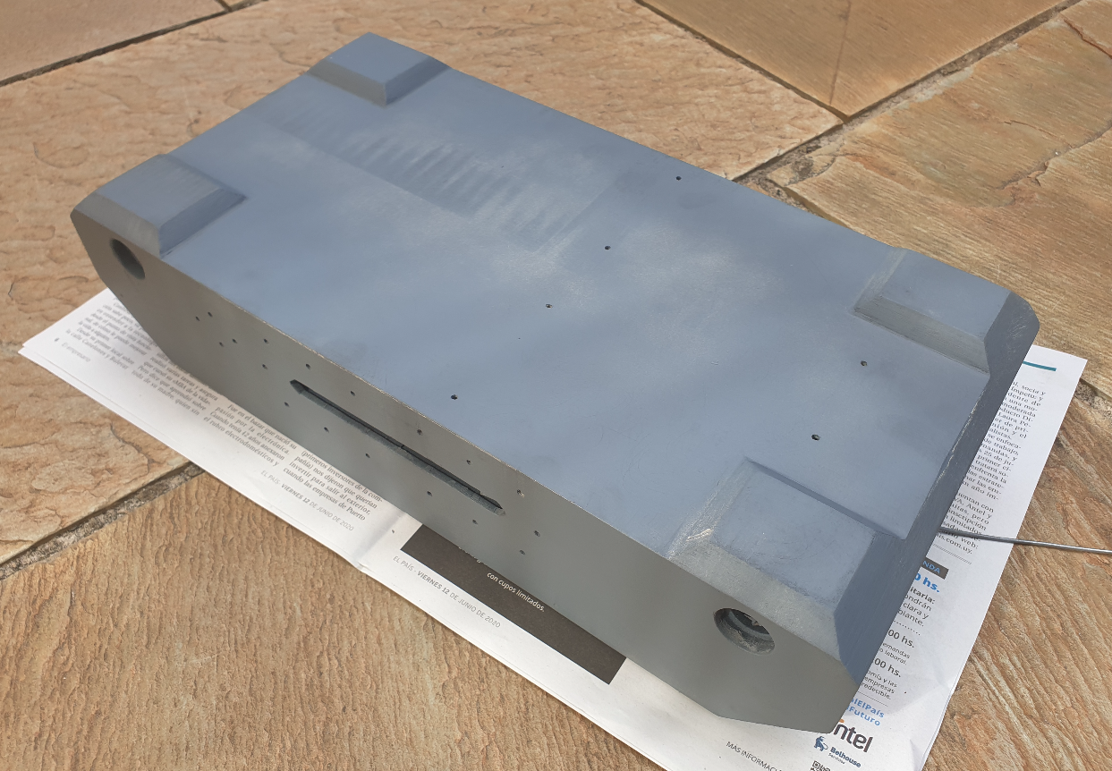
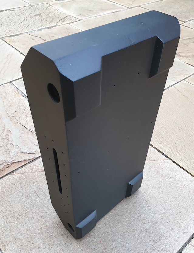
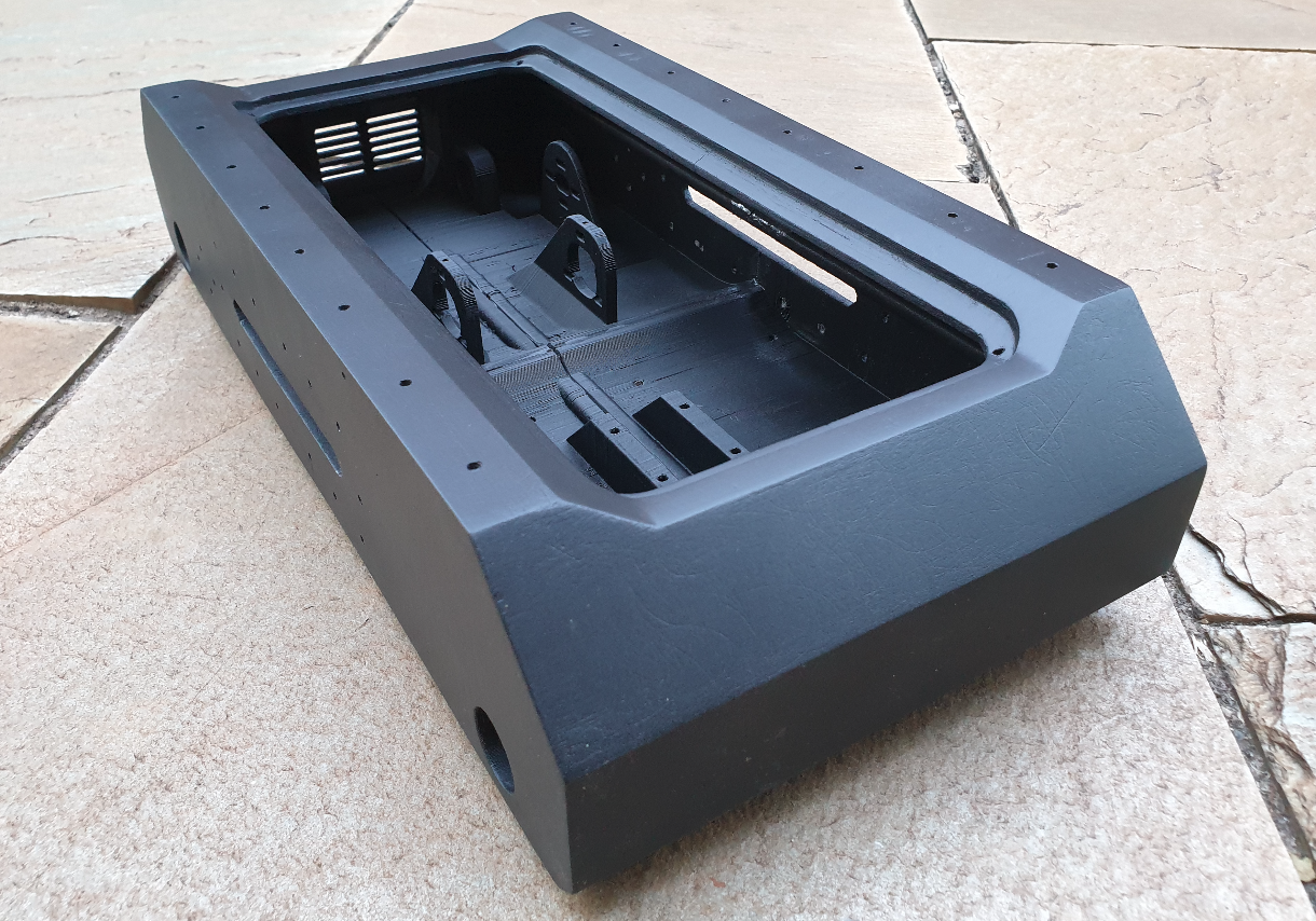
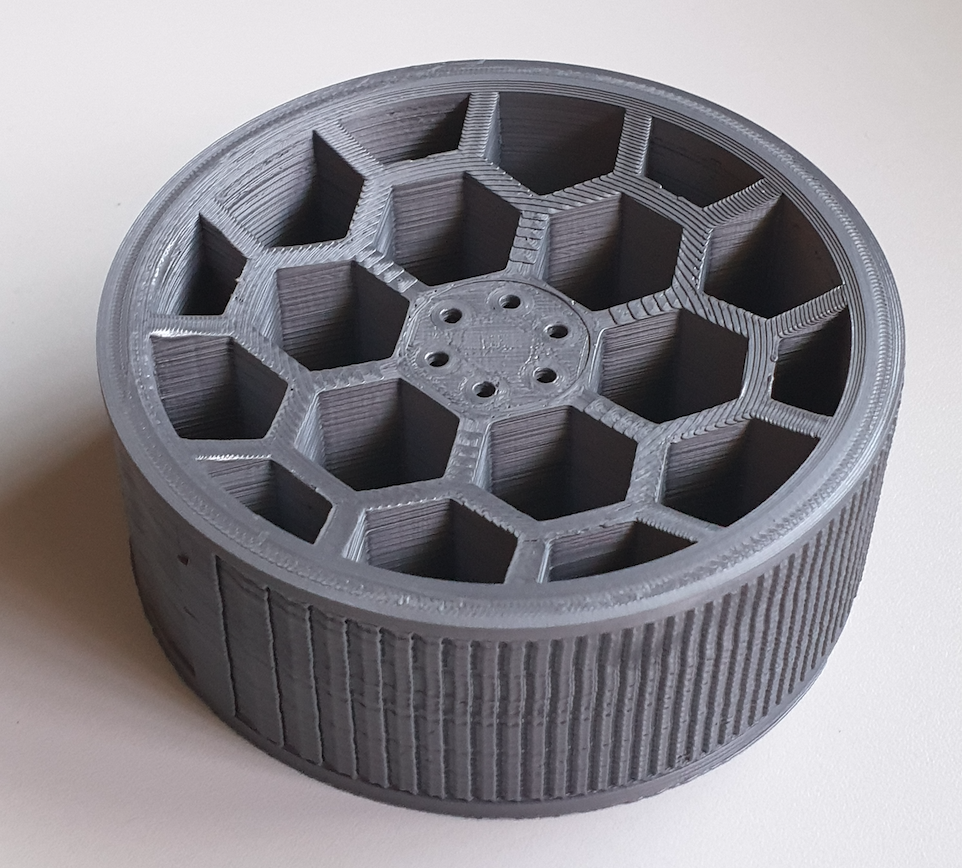
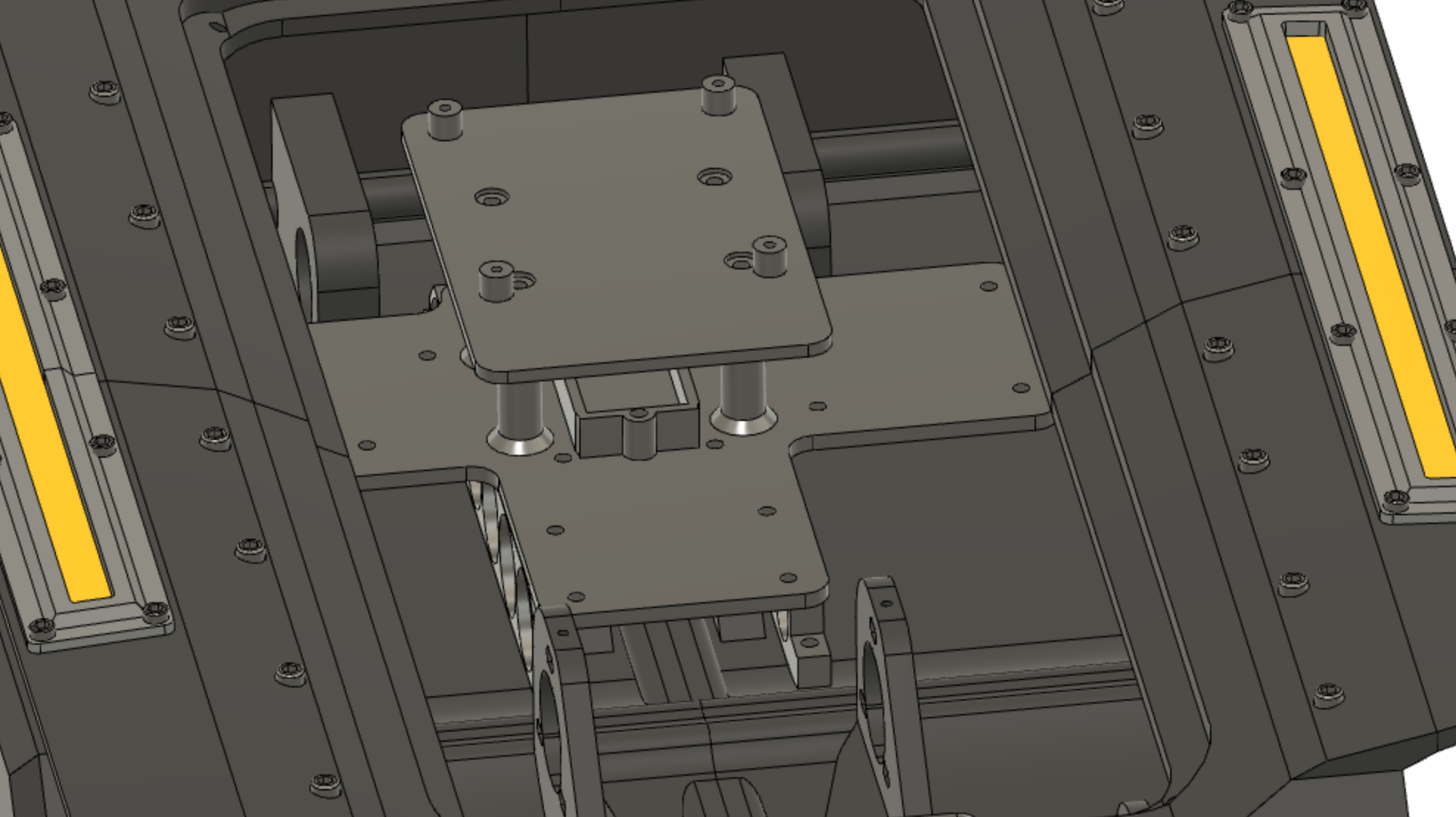
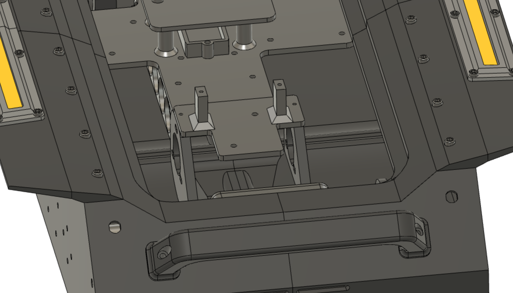
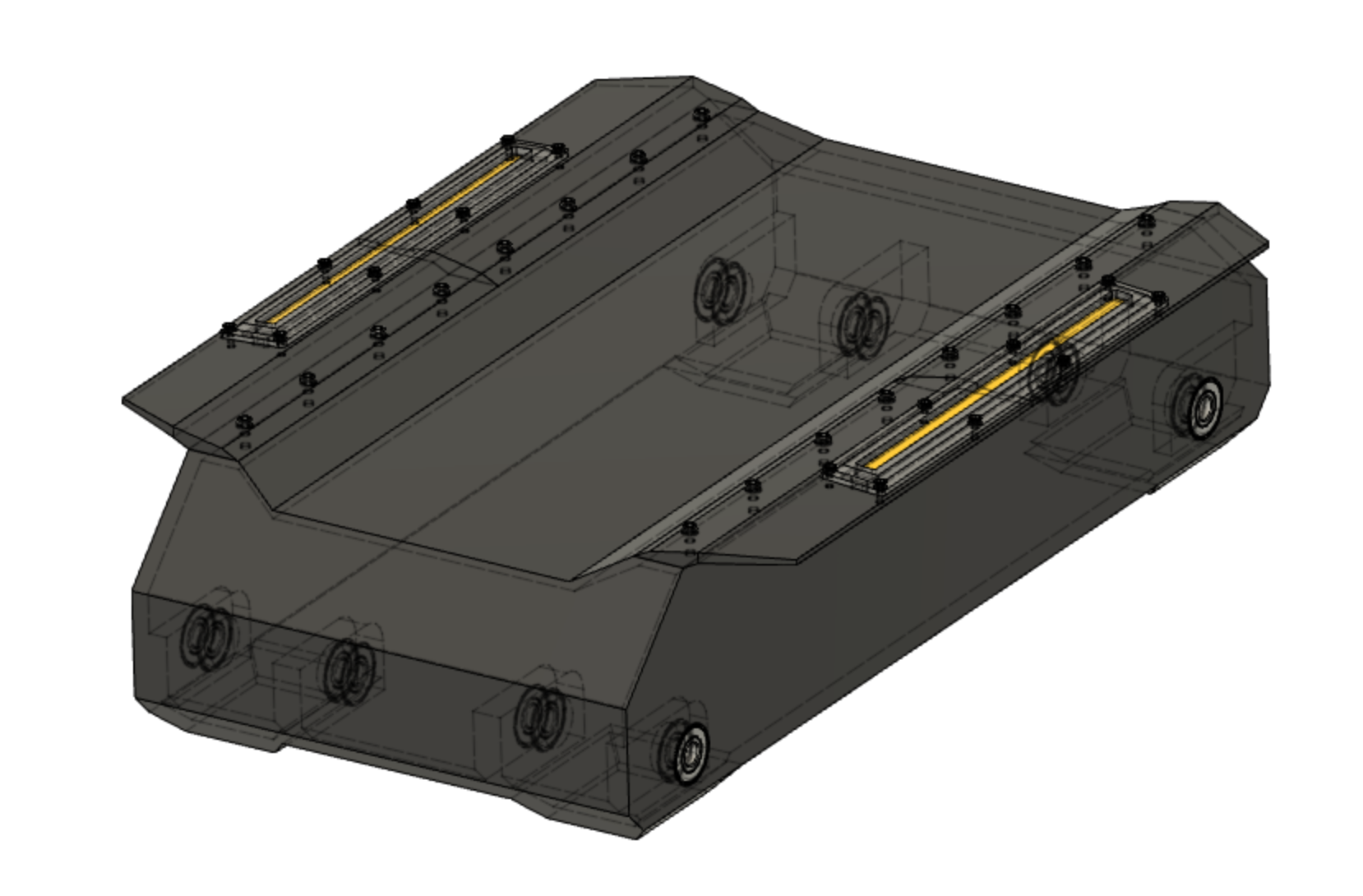
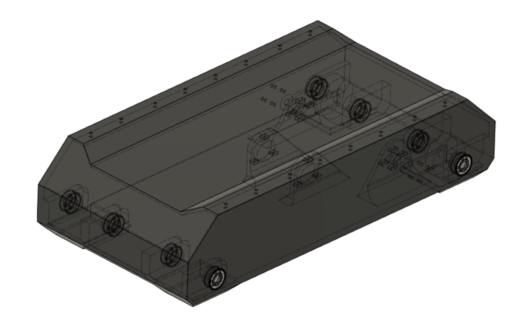
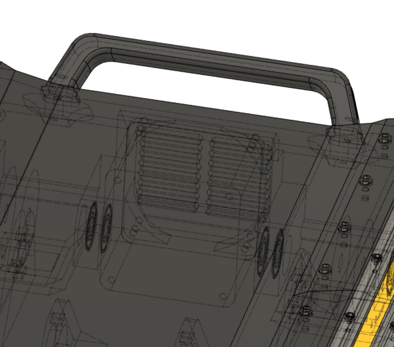
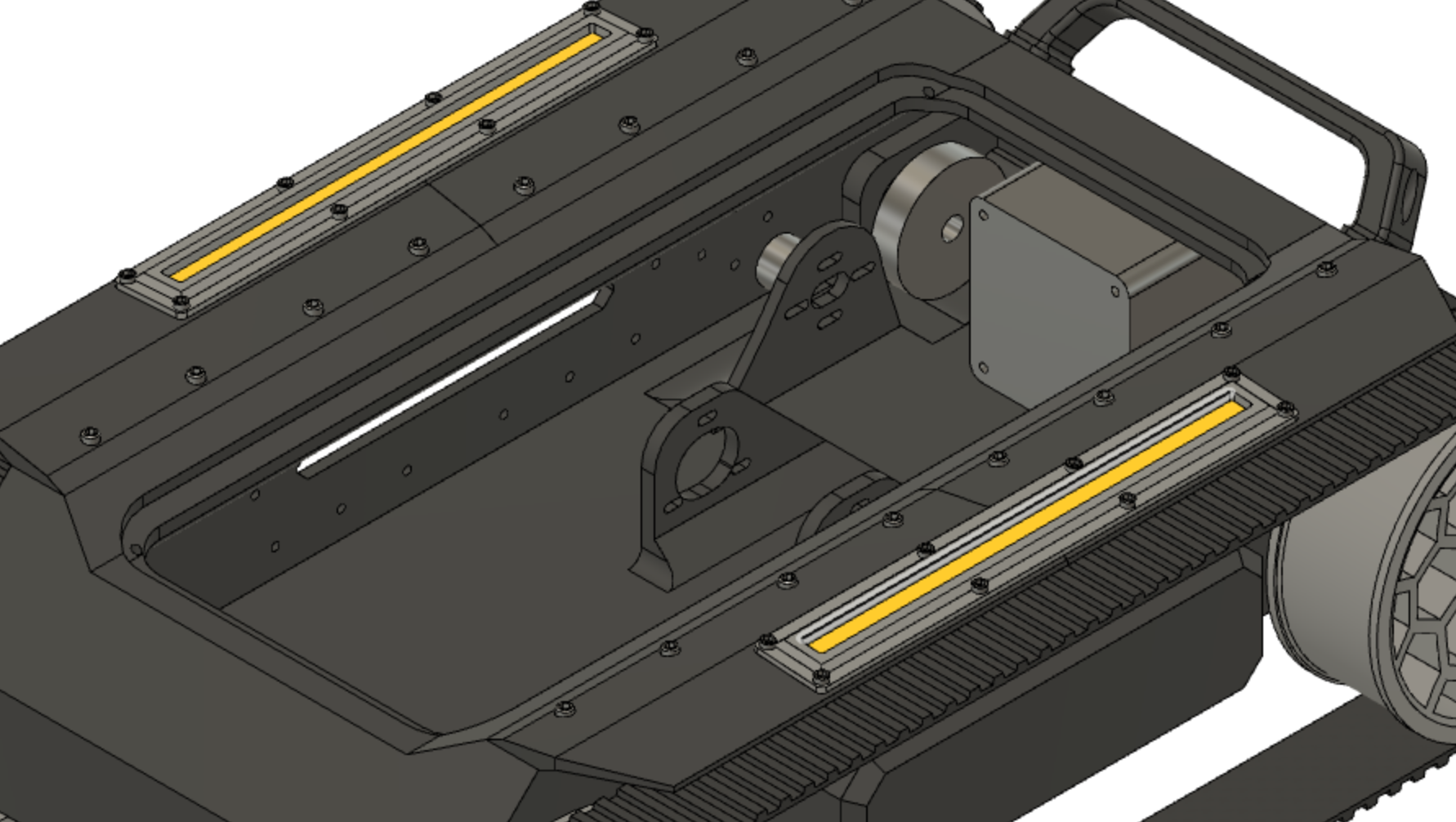
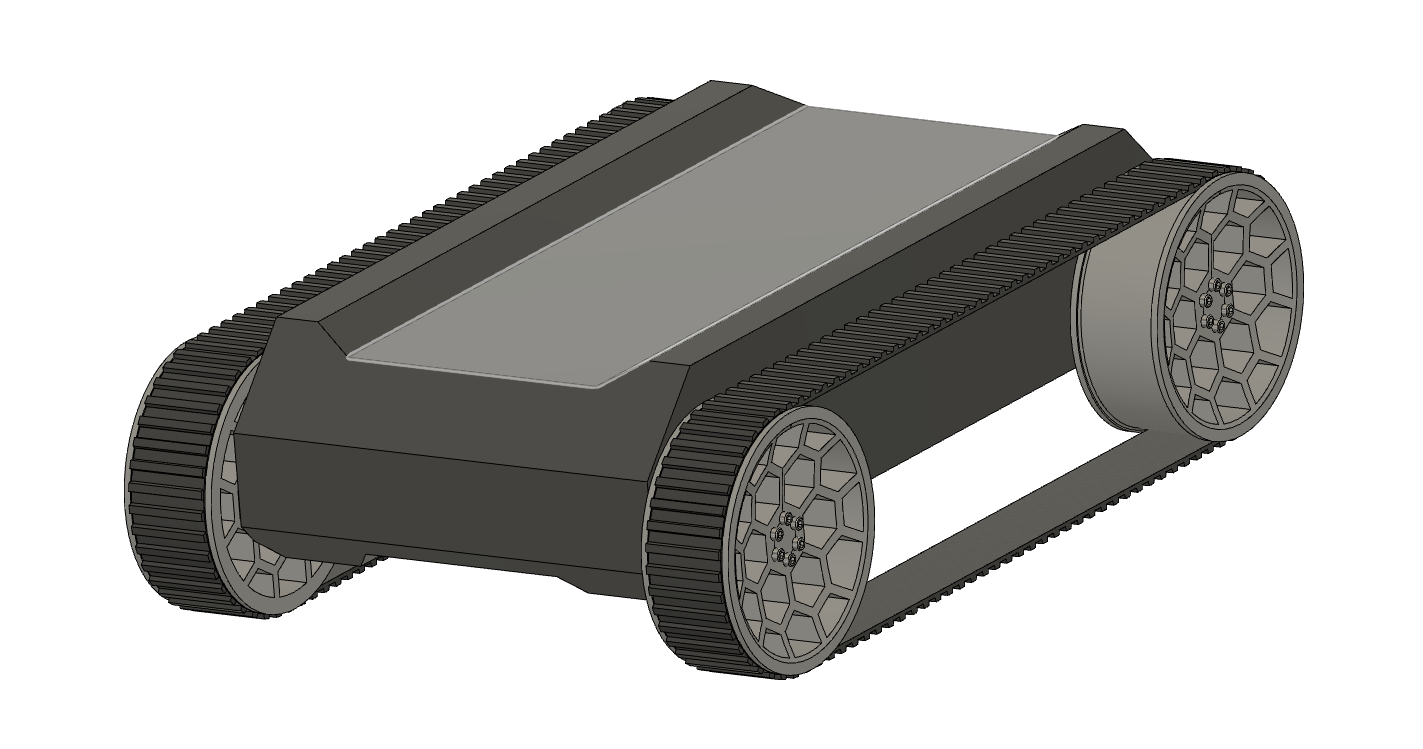
Most of the chassis is 3d printed, which was a challenge on itself. It widely exceeds the dimensions of my 3d printer so I had to slice it into 4 pieces. Why not making the cover see-through? Internals are cool!
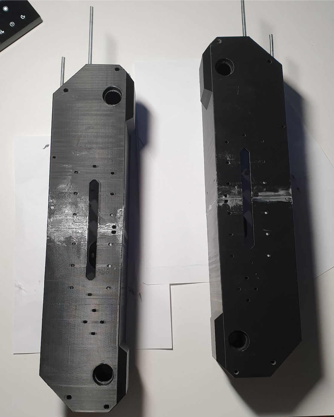
I am making this post after I have completed the design. When I began, I already had an idea of what I wanted it to look like. Trying to give some insight and share some thoughts that came along the design and build. The final model required multiple iterations and features redesign. Reprinting of a couple parts was necessary as well.
With the right tools, I believe this project can be scaled up perfectly and some features I had to add to assemble could be removed. I used what I had available.
I hope it can serve as inspiration for someone.

The idea is to use this platform with ROS, and learn by doing.


 ThunderSqueak
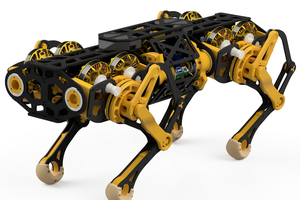
 Ahead
Ahead
 Pinomelean