 Maximiliano Palay
Fenders
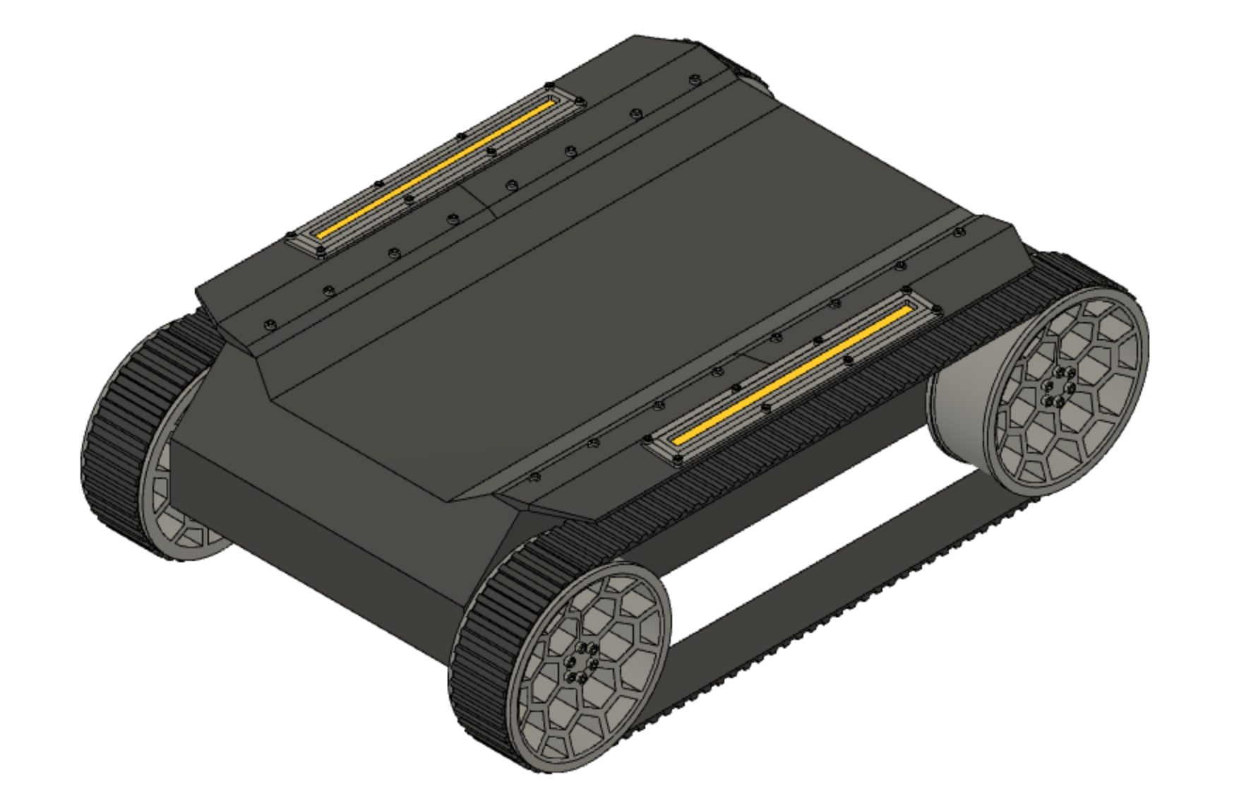
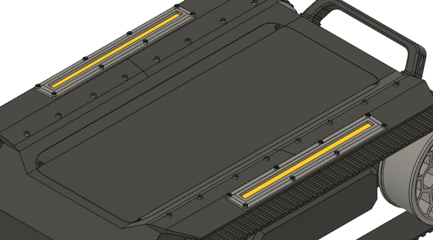
Before getting into designing the interior, I wanted to leave the outer body in a further stage of development. I thought about doing a couple of fenders, as some tanks and robots have above the tracks. Perhaps I could also mount some warning lights on them? Yes! They would go great with some amber LED strips for cars I have bought. These would be some kind of warning lights, so the robot is properly noticed when powered on and moving around.
These will be attached to the frame with screws, and a cable will run from the side of the body towards the LED strip.
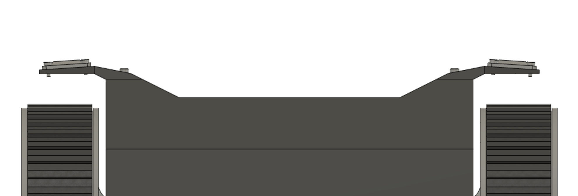
You might notice these are cut in half, because they won't fit in my printer. I'll have to print the halves and paste them.
This same problem will be addressed for the body. But I'll probably need to cut it in 4.
Interior
Made a shell out of the body and started [blindly] with the interior. I won't make an opening yet, but this will probably require a top lid for easy access to internals. I'm still figuring out how I'll make it.
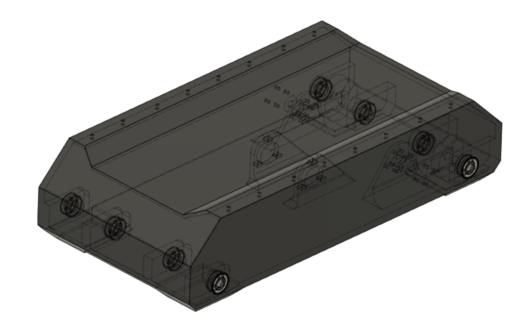
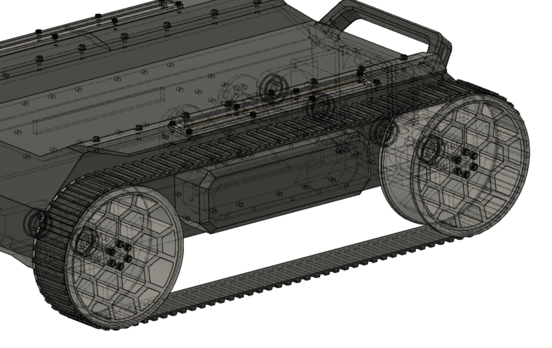
To begin, a good task is to accommodate bearings to hold the 4 wheel axles. You can see this in the following picture, viewing hidden lines as dashed lines.
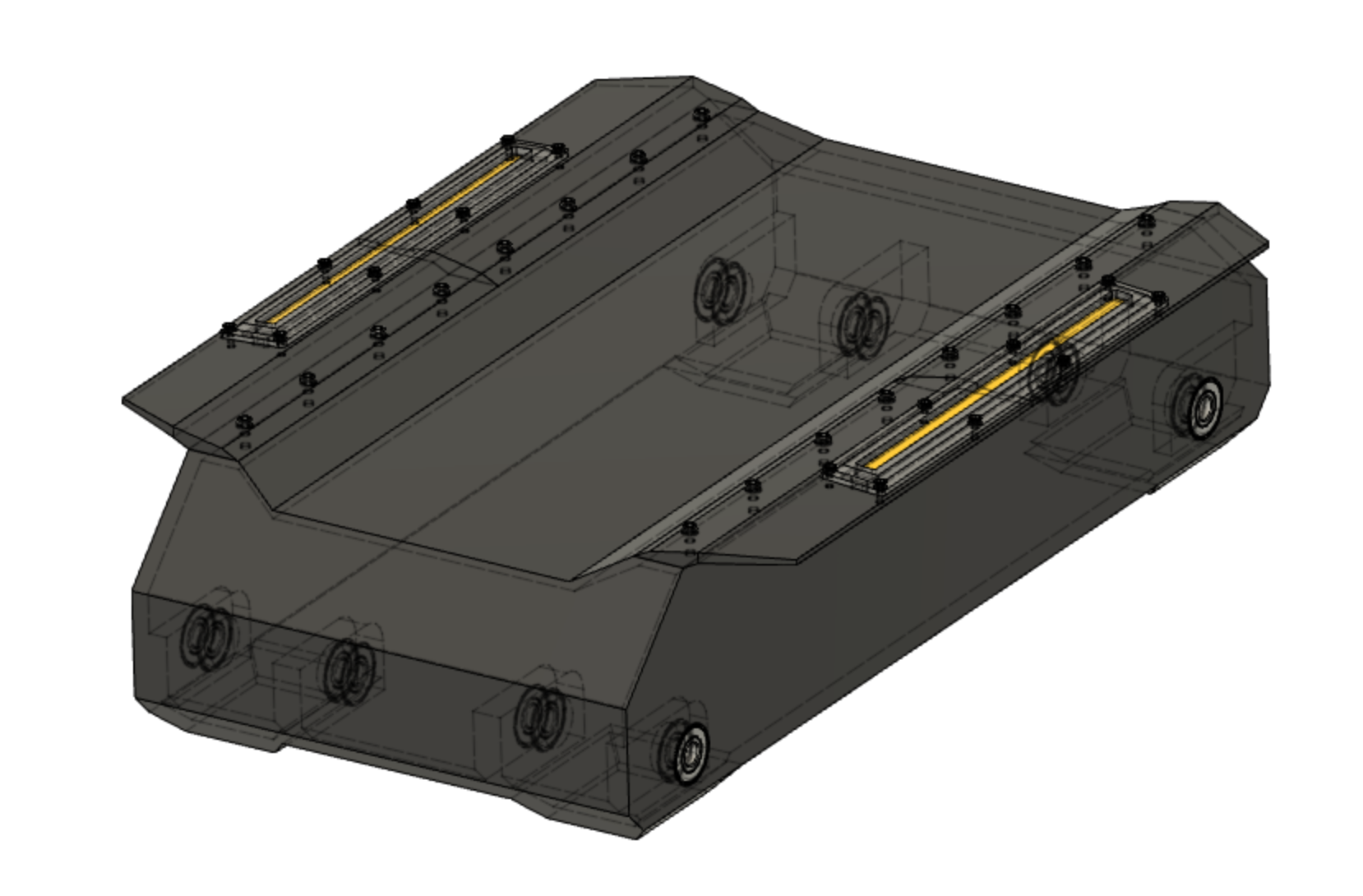
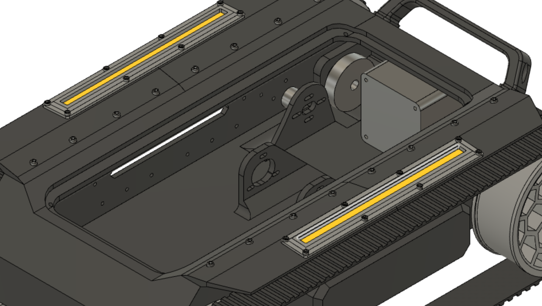
Having the belts [200mm GT2 timing belt], pulleys [20 tooth GT2 pulley, 6mm bore and 60 tooth GT2 pulley, 8mm bore] and motors [Turnigy Multistar 3508 268kv, with modified long 6mm axis], the next step was incorporating the motor mounts to the chassis. Encoders as well! These will be coupled to the shaft on one side of the motor through a 1:1 transmission with same belt, while the other side will be coupled to the wheels through said belts and pulleys.
Left some holes on the body to allow for easier fitting of the motor screws.
It is very important to think how things will be assembled. Sometimes the design is great but it's almost impossible to put together. Although I tried to have this in mind, you'll see I made some of these mistakes. The holes turned out to be useful, but it was actually very difficult to put the screws in place.
Handle - A jump to the outside for convenience
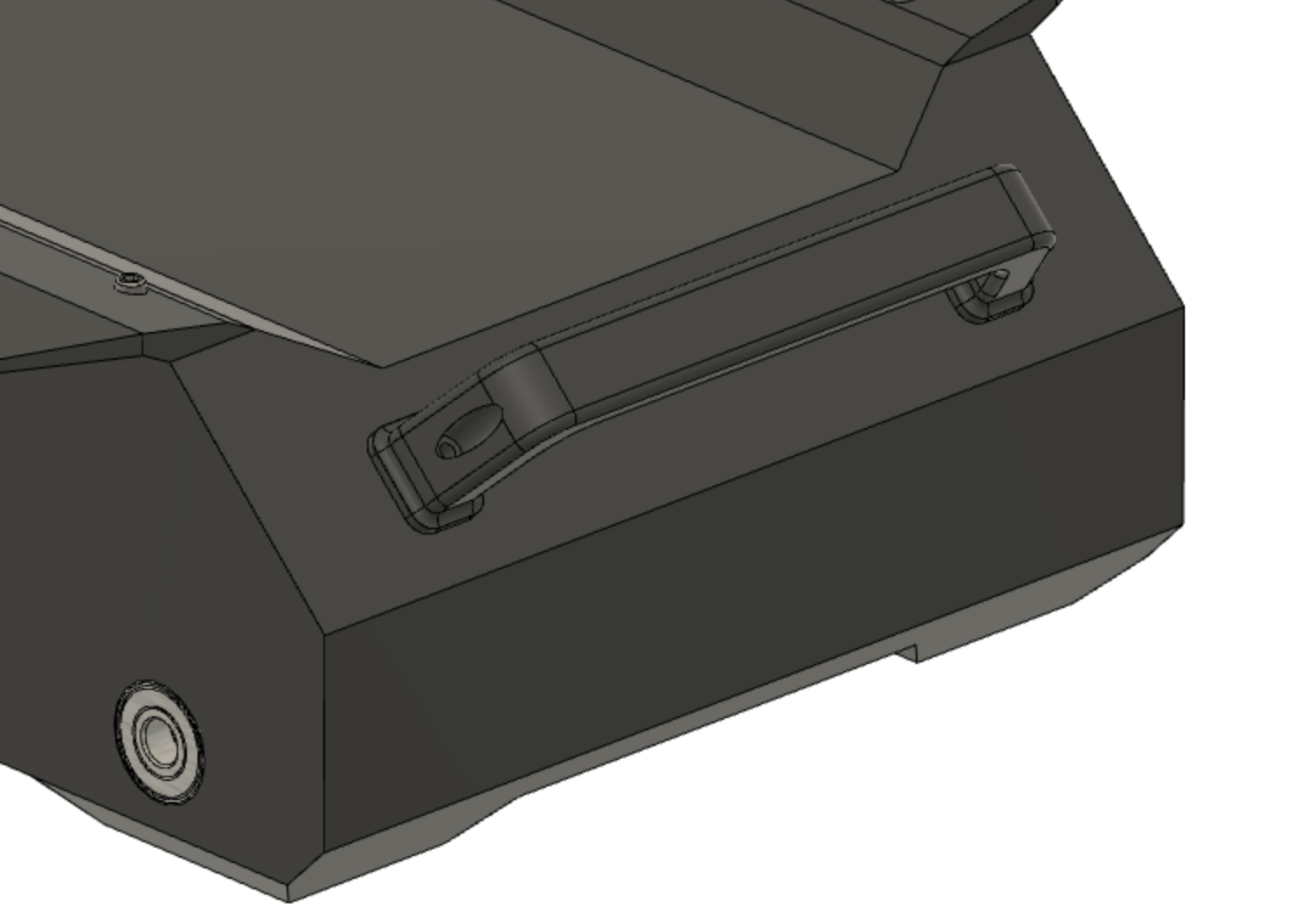
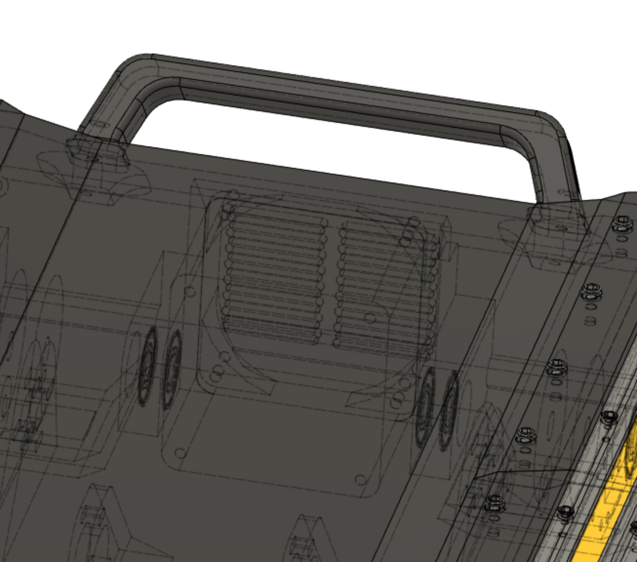
Getting ideas from the internet, I decided to include a handle. The size and proportions were "guessed" comparing with a drawer handle and getting my hand in it. It is at an angled face, so it is easily accesible and the screws don't pull straight out. Besides, the top is reserved for a removable cover and the back side will have another feature, which I will cover next.
Cooling
I'm thinking front to back airflow, with cool air coming in from the front, going through all the electronics, and exiting at the rear side. A grill resembling that of an M1A1 could look good. I'll use an old server fan with speed control, which is a total overkill, but I prefer using it than buying another one. Perhaps, having plenty of air volume circulating can dampen the effect of horrible airflow, which I will not get into optimizing.
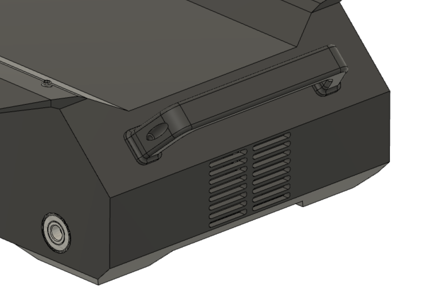
I actually like the look of it! Let's hope it is actually functional. There's a socket that holds the fan inside with 4 screws.
Back to the body
You can see the body in the second picture. I'm thinking the section in between the wheels is a bit empty. Perhaps this space could be used for batteries, or some other components. I could make detachable compartments, but don't want to add a lot of complexity. I'll make some modules that will be fixed, and held from inside out with screws. This will require an opening in the body to allow for cables going through. No screws will be visible from the outside.
Removable top cover
After some thoughts and tries, I finished up with this lid. It is held by 4 screws, and lays on/in a recess.
Design took much longer than I anticipated. There were many considerations and redesigns. On the next post I'll try to round up the design.
Discussions
Become a Hackaday.io Member
Create an account to leave a comment. Already have an account? Log In.