 Maximiliano Palay
Preparing the body slicing
Knowing I would slice the body in 4 pieces, I would then have to fuse the printed parts into a monocoque. Using just glue didn't make me feel too optimistic about it, though it could have been enough. Instead, I decided to include some plastic guides to join everything using 3/16 threaded rods. I put several in each direction to ensure everything would stay in place. The rod would make the thread as it went through the plastic. With some glue to fill the joints and with the strength and weight of the threaded rods, the body ended up super rigid, and with a nice, hefty weight.

Battery trays
The batteries I would be using were 18650 cells, in a 6s2p configuration. I decided to make two modules in parallel. Designed a minimal frame to hold each seat of batteries, mounted on the bottom face to keep the COG low.
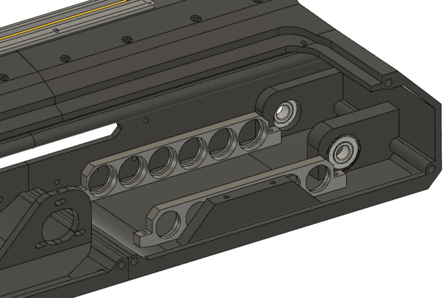
The chamfered feature that can be seen before the battery holder is to allow for mounting plates that accommodate electronics above.
Mounting the electronics
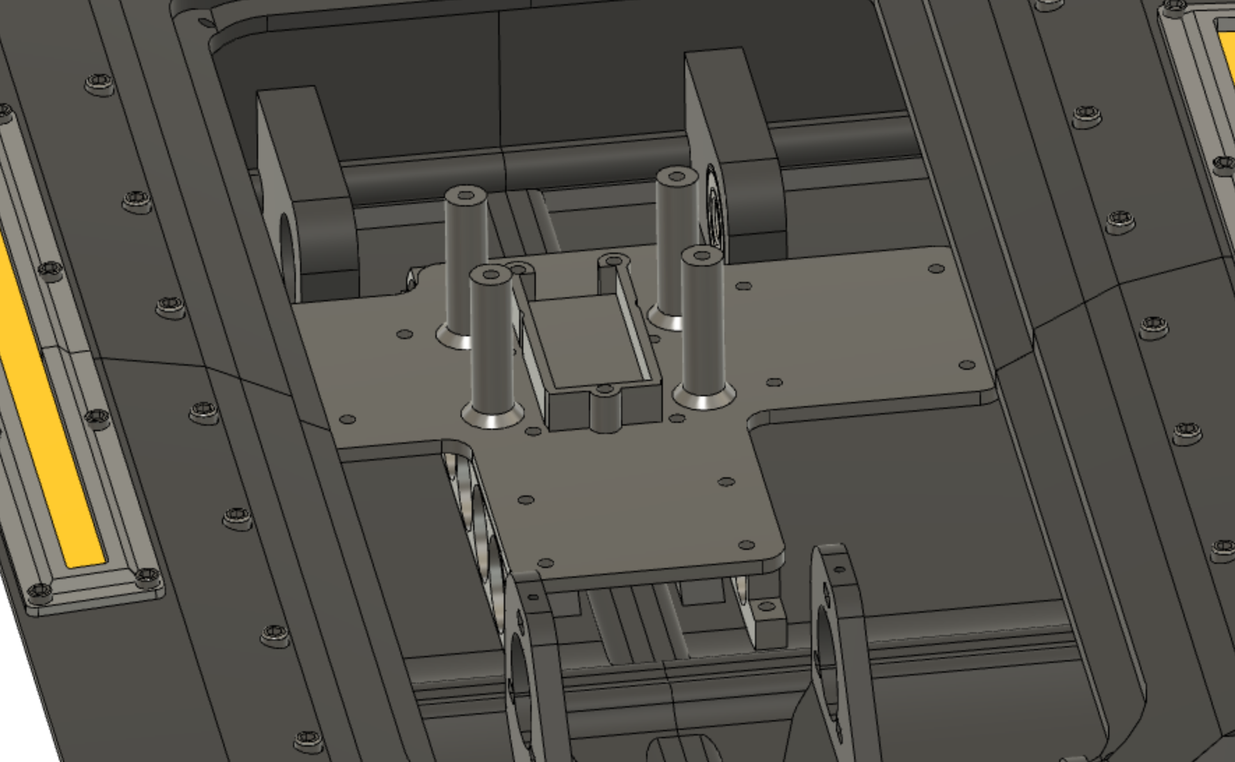
I went for a stack design, that allows me to assemble everything easily, with the disadvantage that to make any changes on the bottom layer, I would have to remove the top one.
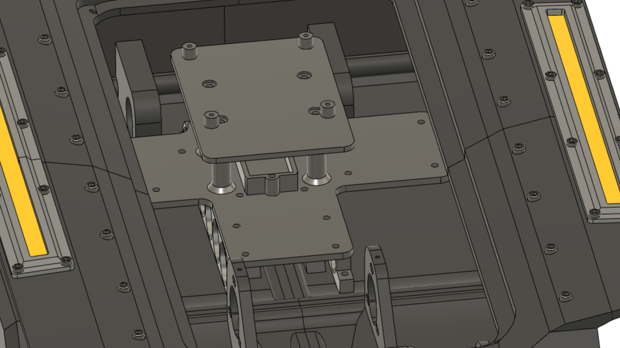
The first layer, would hold the Odrive, an Arduino Nano, the L298 H bridge module to drive the LEDs, and a couple DC buck converters to power 5v electronics.
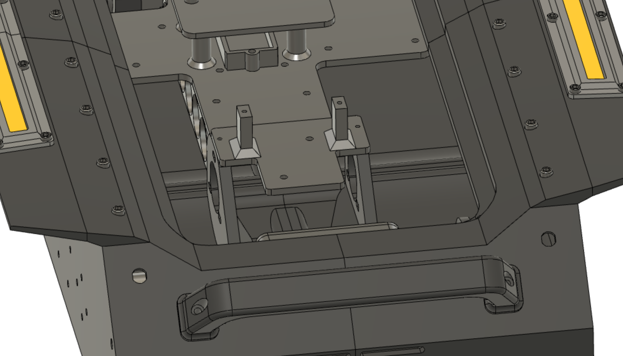
The Raspberry Pi would be on top of that, so made a small plate to be mounted on over this one.
The remaining component was the wireless adapter, which already had a frame I designed on a previous project. I made a small plate that accommodates a 5v DC buck converter and the wireless card. This particular one has two antennas. I decided to make two openings to mount these on the back, but as high as I could.
The lid (yes, again)
Having the electronics mounting resolved, I saw there wasn't much clearance between the Raspberry Pi and the top cover I had designed at the time. Solved this by offsetting a part of it something like an inch above. This lid would house an easily accesible switch to turn on (ad in case of an emergency, off) the robot, a camera and the lidar sensor.
Although I'm not too happy with how the electronics mounting came out, I love seeing the internals and the technology running this robot. Incorporating an acrylic top would be amazing. So I contacted a couple of sellers and decided to make it with 2mm acrylic. I would still make kind of a lid frame that would give it rigidity and allow for attaching to the body, and make something like a window in the middle.
Remember that thing I mentioned about front to back airflow? Yes, that needs to be addressed as well. Mounting the camera on top? Yes, that too. Perhaps some mounting holes that allow to mount different things, and design the accessories to be mounted with those holes in mind. Kind of a modular design.

You can see a big hole for mounting the lever switch, vents on the front face, holes and a channel for the CSI cable of the Pi camera. The acrylic could then be modified to mount anything on top as well!
The same concept of slicing applied to this part. Two threaded rods go through the sides.
Camera & lidar
Made a small, simple camera mount. The camera slides in from the back, and is held by four m2 screws. If I mounted the Lidar just as It came, it would have a couple of things blocking its field, such as the camera, the on/off switch and the antennas. So made a shroud that just raises it from the acrylic the right amount.

Building this won't be easy, but I'll do my best. There's plenty of printing to do. 4+ days for everything.
Some exploded views? Yes, please.
Discussions
Become a Hackaday.io Member
Create an account to leave a comment. Already have an account? Log In.