 Gonzho
Valden Heat Pump Controller v1.x
The Valden Heat Pump controller is an open source platform to precisely control heat pumps. This controller can be used for the automation of newly built Heat Pumps (HPs), as a repair controller for old systems or as control system for performing experiments on refrigeration equipment.
Further details, appendices, fine-tuning options, illustrations, abbreviations, and so on you can find in the permanent repository: https://github.com/openhp/HeatPumpController/ .
Specs
- 12V 0.5A DC power supply,
- 230V output,
- 4 16A relays: Compressor, Hot Circulating Pump (CP) or Air Fan, Cold CP or Air Fan, Crankcase Heater,
- 2 inputs: Hot and cold side refrigerant over/under pressure NC sensors,
- up to 12 temperature (T) sensors, -55..+125 °C range,
- Electronic Expansion Valve (EEV) supported, 6 pin EEV connection: 4 * coils + 2 * 12V,
- automatically turns on/of system when heating required,
- automatic power saving mode,
- built-in protections: cold start, overheat, short-term power loss, power overload, ground loop freeze, compressor protection against liquid and other,
- LED indication,
- control via remote display https://github.com/openhp/Display/ or local Serial (UART 5V).
Refrigeration schemes supported
- Heat Pump (HP) with Electronic Expansion Valve (EEV),
- HP with capillary tube or TXV,
- EEV-only controller.
Installations supported
- Indoor: a house or technical building with an almost stable temperature,
- Outdoor: harsh climatic conditions taken into account. Outdoor HP installations tested down to a minus 32 °C.<br><br>
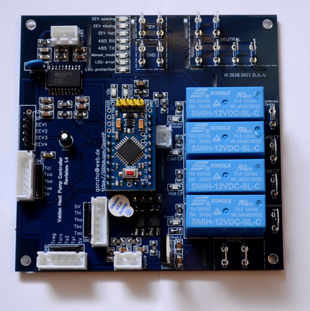
Get your own PCB copy. Assembly.
- download PCB Gerber file here or get your own copy there,
- order electronic components, see BOM (Bill Of Materials) appendix,
- solder electronic components, assembly instructions here.
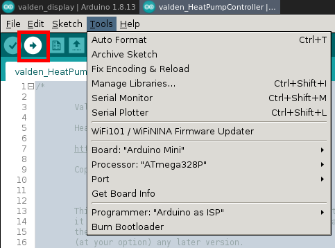
Firmware upload
This process is the same as for other Arduinos:
- connect USB-> UART converter,
- start Arduino IDE,
- download and open the firmware file,
- select board and MCU in the Tools menu (hint: we are using "mini" board with 328p MCU),
- press the "Upload" button in the interface and "Reset" on the Arduino.
For arduinos with an old bootloader you need to update it. (Tools-> Burn Bootloader).
For successful compilation, you must have "SoftwareSerial", "OneWire" and "DallasTemperature" libraries installed (see Tools -> Manage Libraries).
For the first time it's enough to upload firmware without any tuning. Think of it as of a commercial closed-source controller, where you cannot fine-tune internal options. And any other manual configuration do not required too, just upload firmware. You will see an error LED indication and hear a beep, since no sensors connected to your controller. Follow the next steps.
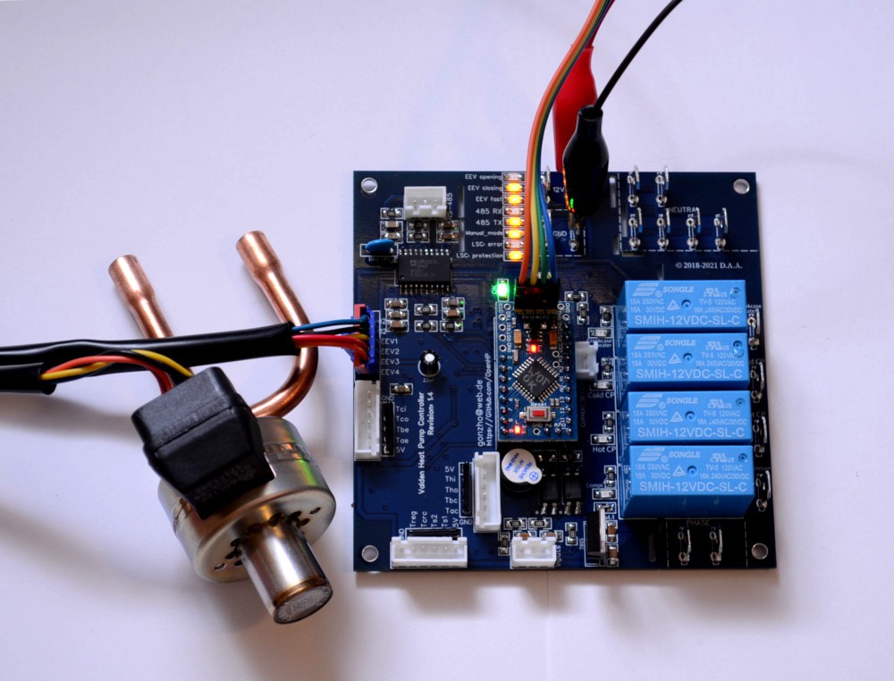
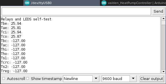
Self-tests
QA tests are available to test the assembled board.
Self-test helps you check relays, indicators, speaker and temperature sensors.
To run a self-tests:
- uncomment this 3 defines in source code header,
```
//#define SELFTEST_RELAYS_LEDS_SPEAKER //speaker and relays QA test, uncomment to enable
//#define SELFTEST_EEV //EEV QA test, uncomment to enable
//#define SELFTEST_T_SENSORS //temperature sensors QA test, uncomment to enable
```
- upload firmware,
- connect 12V power supply,
- disconnect +5V wire from USB-UART converter.
To check EEV connection, you can use a stepper motor. If you are testing a real EEV, it will be closed after the first "beep" and partially opened after the second "beep". If it's not, check if stepper or EEV center pin(s) connected to +12V and try to swap coil-end pins (EEV1..EEV4).
To check temperature sensors connectors crimp one array of sensors. Plug it to all sensor connectors one-by-one and check results in a serial console.
After tests completed, comment 3 self-test defines.
Choose your installation scheme and uncomment one of those options:
```
#define SETPOINT_THI //"warm floor" scheme: "hot in" (Thi) temperature used as setpoint
//#define SETPOINT_TS1 //"swimming pool" or "water tank heater" scheme: "sensor 1" (Ts1) is used as setpoint and located somewhere in a water tank
```
Re-upload firmware. Your controller is ready for the first start (after wiring). Probably you'll never need to change other options.
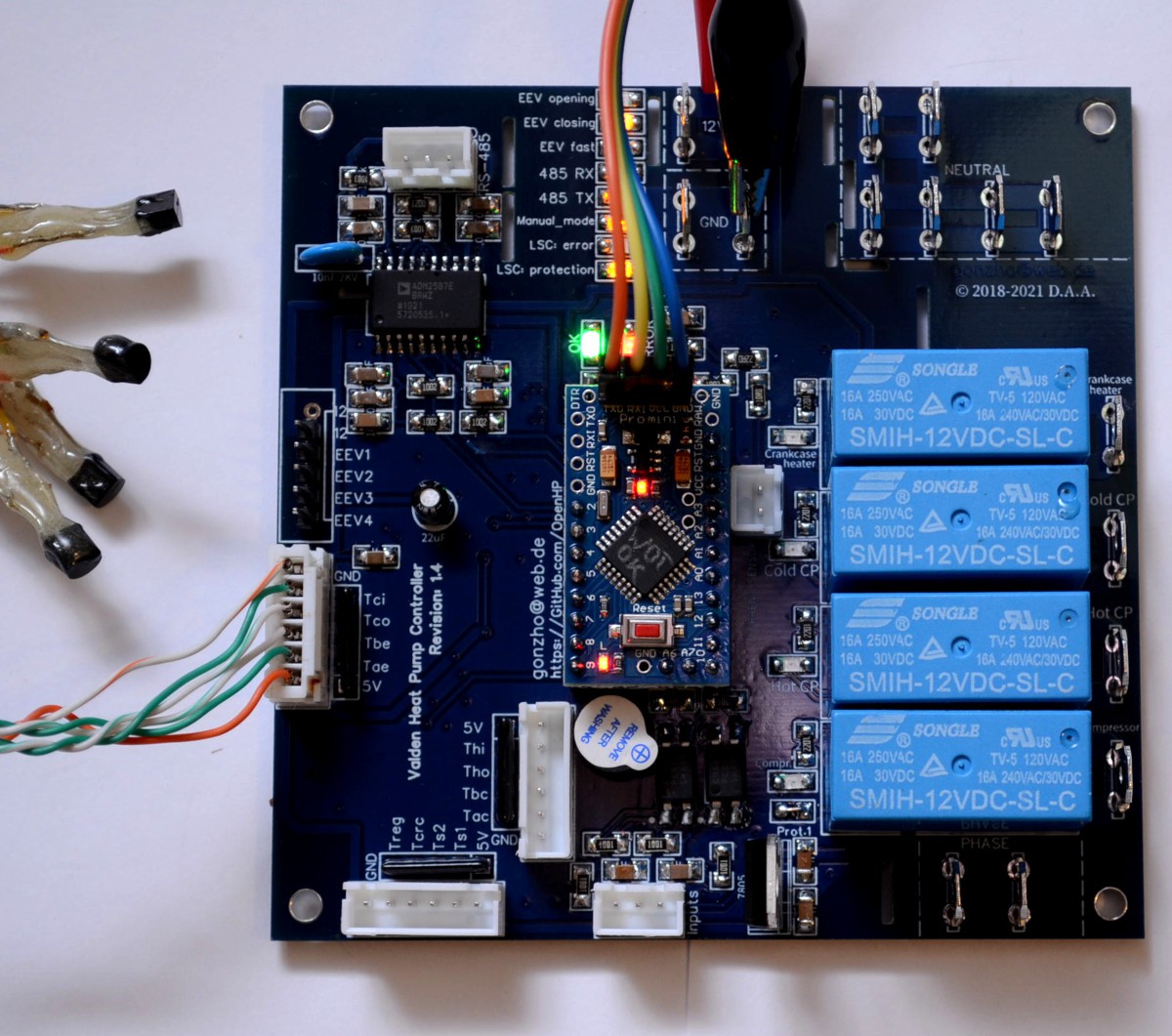
Wiring (permanent controller installation).
Here are no instructions for choosing the right placement for permanent installation of the controller. It depends. You're building your system, and you know much better "where" and "how".
Assuming you have installed your controller to the permanent place, the next step is wiring.
Wiring is very simple, despite a lot of terminals.
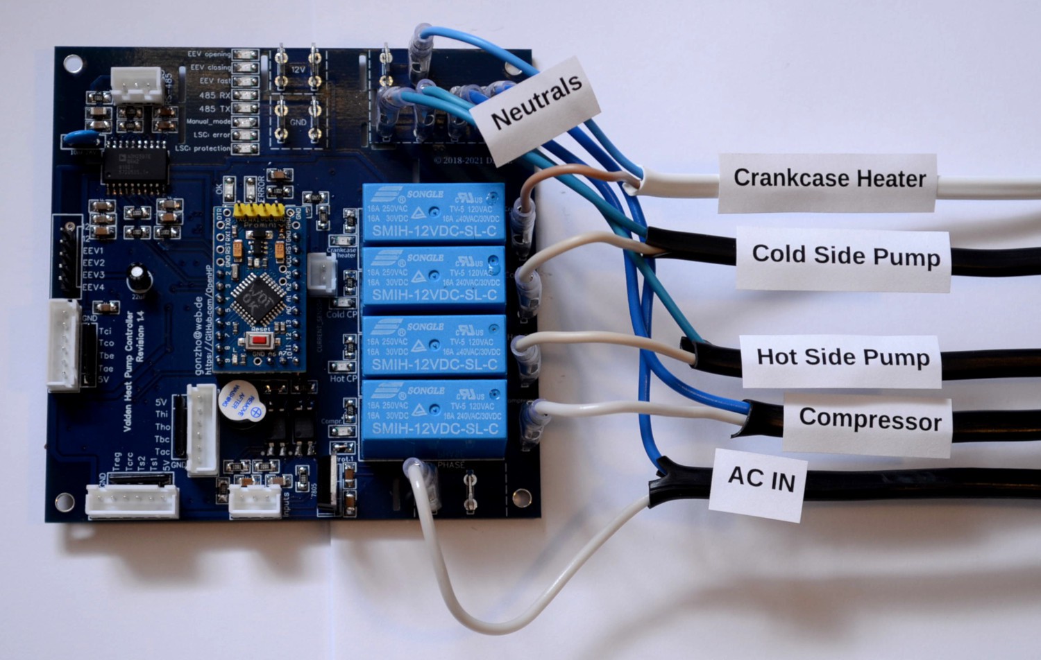
Phases (1st wire in electrical cables):
- connect the "power inlet" wire to one of the "phase" terminals,
- connect the "Compressor" relay output to the Compressor input,
- connect the "Hot CP" relay output to the Hot Circulation Pump input (or to the fan power input of the indoor unit if you are using an air system),
- connect the "Cold CP" relay output to the Cold Circulation Pump input (or to the fan power input of the outdoor unit),
- when using a compressor heater: connect the "Crankcase heater" relay output to the heater cable (highly recommended for outdoor installation and year-round use),
- connect all the second wires of power cords to the "neutral" terminals on the board.
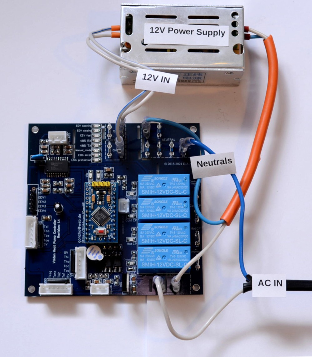
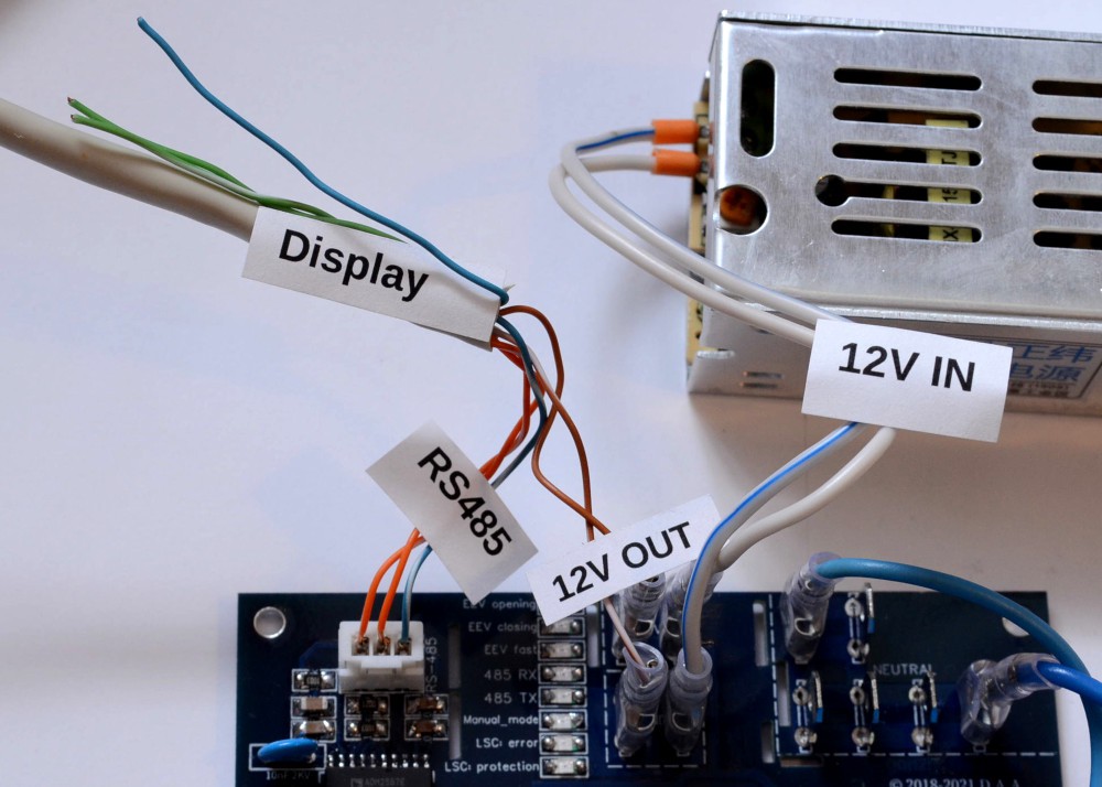
12V Power Supply:
- connect the second "phase" and one of "neutral" terminals to the AC input of the 12V power supply,
- connect 12V power supply output to GND and 12V
Crimp and plug low-voltage connectors:
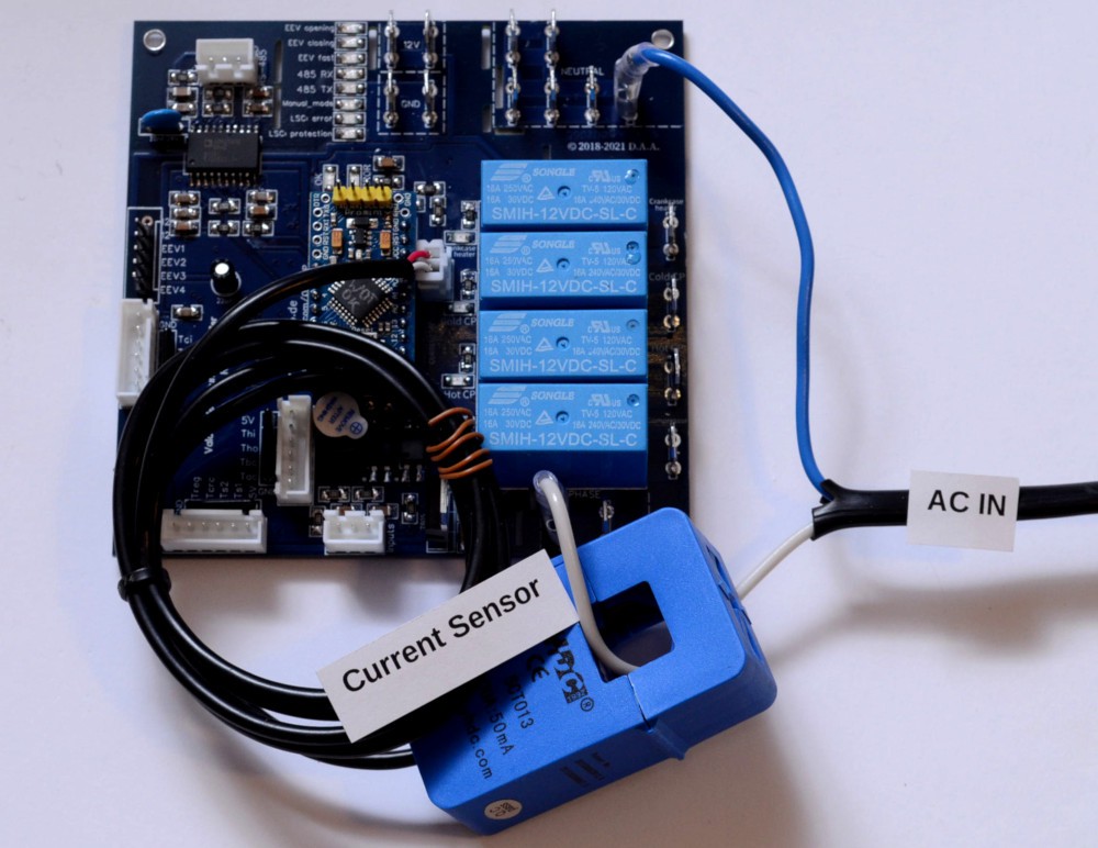
- crimp SCT013 sensor wires (the only one low-voltage device in this circuit with interchangeable wires), connect and install it on the inlet phase wire,
- crimp RS485 to the Remote Display, using a wire of desired length (note that A is connected to A, B to B and GND to GND),
- crimp 12V and GND secondary terminals to the remote display,
- connect EEV to EEV terminal,

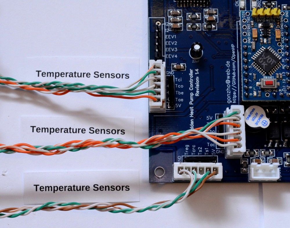
- install all T sensors on pipes, insulate tubes,
- crimp T sensors arrays, you can crimp all four GND wires at every array to one GND connector pin or make 1-to-4 connection somewhere closer to sensors location (same for +5V wires),
- insert T sensors arrays to appropriate terminals (if you do not need to control over all temperatures, disable and do not install unnecessary sensors),
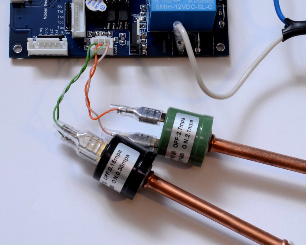
- crimp and plug pressure sensors outputs: crimp 1st wires together to **12V** (right output of the terminal), 2nd cold side wire to the **Pco** (left), 2nd hot side wire to the **Phi** (middle); use the dummy if no pressure sensors used in your system.
You may prefer to solder the wires over using terminals and crimping connectors. But in this case, it will be difficult to disassemble the system if you want to change something. The choice is yours.
And one more: **remember! 230V inside!** Do not turn on the phase without need.
Have you ever received 230V with your own hands? If yes - you know. If no - do not try.
Also remember about animals and children during the installation at a permanent place.
Control and usage: serial console
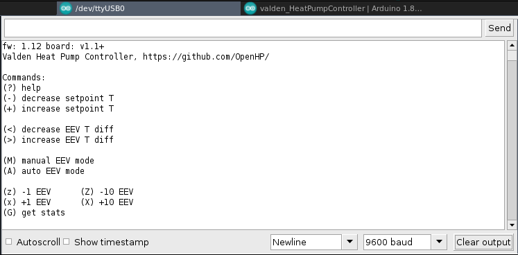
This is a first interface to Heat Pump controller you'll see after uploading firmware (Tools->Serial Monitor).
The console itself is simple to use, several commands are available. Type in command, press "Send". Help and hotkeys:
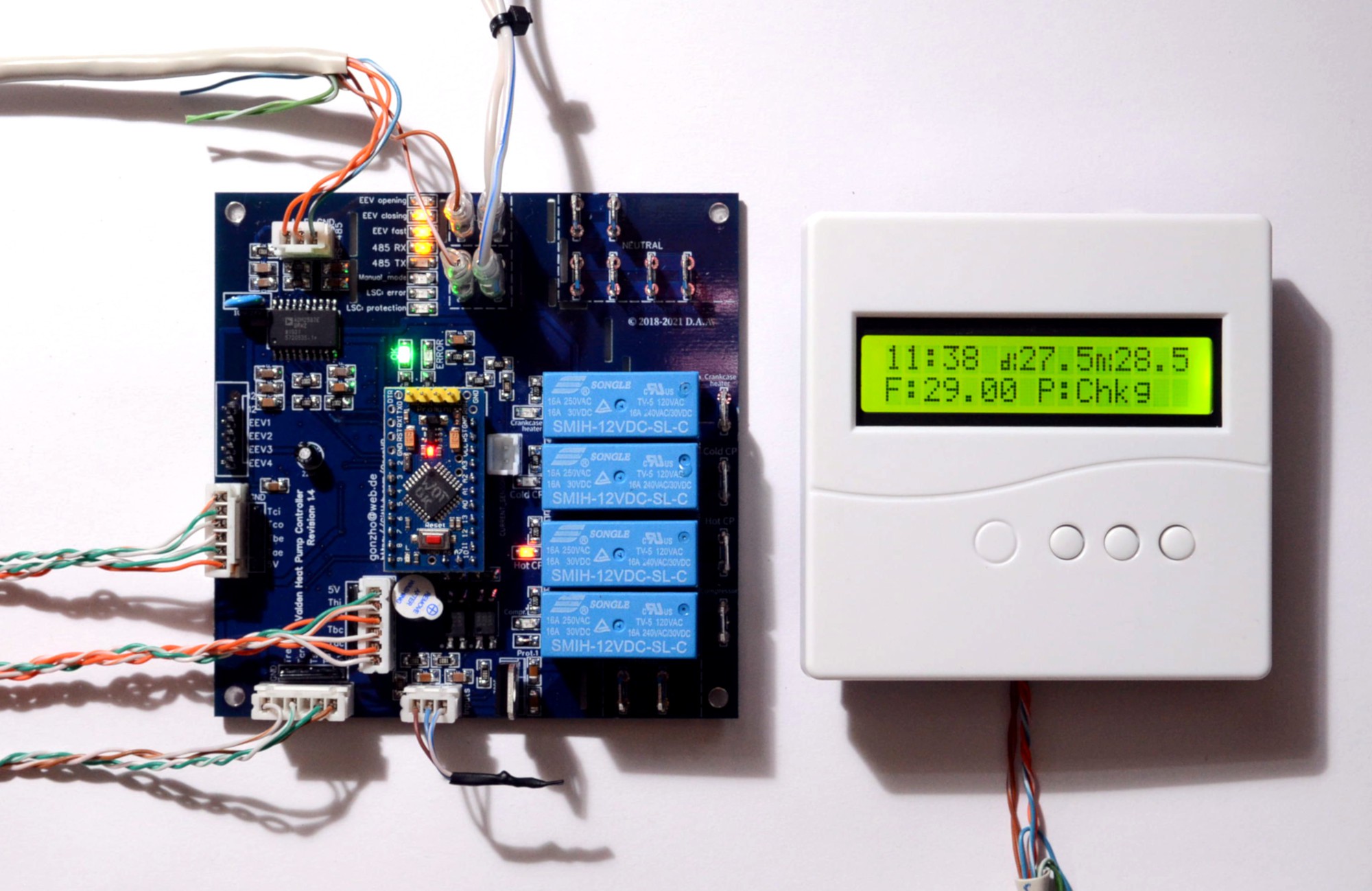
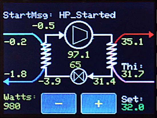
Every 30 sec. (**HUMAN_AUTOINFO** option) you'll see stats. For example, after a startup of your compressor, you'll see something like this:
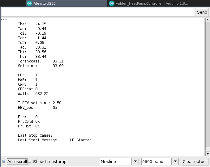
At this example, "hot in" ~30 °C, compressor ~80 °C and so on. Heat Pump (HP, compressor) ON, Hot water pump ON, Cold water pump ON. Power consumption 980 watts.
Abbreviations: refer to Appendix A.
Also, you'll see diagnostic messages in your serial console.
Do not connect +5V wire from USB-UART converter, if you are using a serial console.
Control and usage: Remote Control Display https://github.com/openhp/Display/
This is a way for the end user to control Heat Pump.
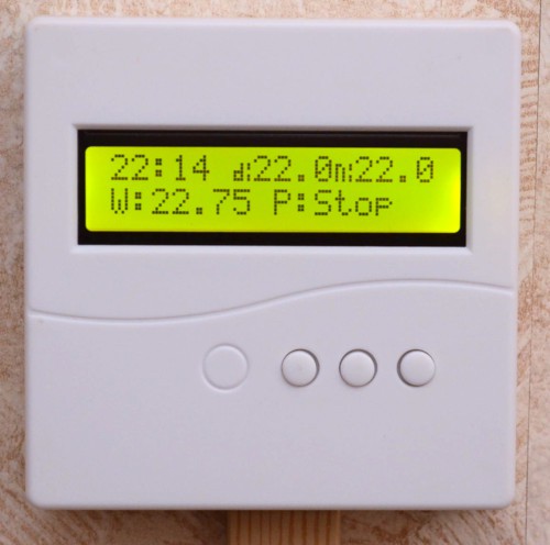
End user does not want to know much about refrigerants, evaporation, discharge temperatures and so on, so this display designed as simple as it was possible. See Remote Display page https://github.com/openhp/Display/ for details. And yes, this display is open product too, with available Gerber, PCB and source code.
Control and usage: Service Display https://github.com/openhp/ServiceDisplay/
One day I've realized that a netbook with a serial console is a good diagnostic tool, but I want a compact tool to get maximum available information from a Heat Pumps. So, this "Quickly Assembled Service Display" appeared. It fits everywhere and with a good power bank it can work 2-3 days long, without any additional power source. The diagnostic display is build from scratch, no PCB and housing here (and no plans to create it), because I do not see this service display as a permanently mounted device.
If you want a compact and visual tool - this device is for you, so check the Service Display Page https://github.com/openhp/ServiceDisplay/
Starting up the heat pump system for the first time and charging refrigerant
This is an easy part, but if you don't have experience it will take time.
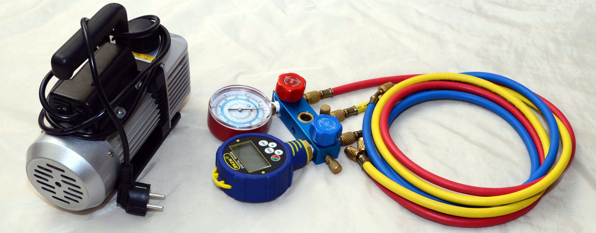
You have performed a pressure test and vacuuming. It's time to charge your system.
Let's say you don't know how to calculate the amount of refrigerant in a recently built system, so follow next steps:
- charge a small amount (for example 300 g) of refrigerant,
- get ready for a system protective stops by Tae or Tbe temperature, this is a normal system behavior while refilling refrigerant,
- power on your heat pump,
- after compressor startup suction temperature will be about -20 ...- 40 °C (according to the suction pressure on the pressure gauge),
- for single-component refrigerants: slightly open the valve of the HVAC gauge manifold and start adding refrigerant through the gas phase on the cold side,
- for multi-component refrigerants: turn over the refrigerant cylinder, VERY SLIGHTLY open the HVAC manifold valve and start adding VERY LITTLE amounts through the liquid phase,
- continue, until the suction temperature (according to the suction pressure on the manometer) is ~ 10 ... 12 °C lower than the temperature of the heat source (example: the temperature at the inlet of the mixture of water and antifreeze from the closed ground loop is + 8 °C, so the suction temperature should be -2 ..- 4),
- close the manifold valve,
- at every step check the discharge pressure: it should not be above the discharge sensor temperature (Tbc),
- wait for the system to heat the target to an almost stable temperature, add little amounts of refrigerant while temperature increases (and suction decreases),
- stop if you are sure that the heating process proceeding slowly,
- take a final look and charge when the system is stable and the heat pump stops normally (setpoint is reached), this may take 12 hours or more,
- after the final refilling difference between the suction pressure temperature and the Tae sensor temperature should be 3 ... 6 °C.
This algo is good and safe both the first time and as a starting point. As you gain experience, you will get yours much easier and faster.
Also, use "manual EEV mode" during refilling process.
Keep your eyes protected and do not freeze your fingers.
Hints
For more information about Heat Pumps look at Wikipedia HP page https://en.wikipedia.org/wiki/Heat_pump .
If you want to know "how the refrigeration systems work", read Patrick Kotzaoglanian books.
If you want more technical details, sophisticated schemes, "how EEV can be driven by temperature" diagrams, etc. refer to vendor manuals (you'll find all you need in the Alfa Laval brochures, Danfoss guides, and so on).
For refrigerants and oils types comparison see wiki.
Personal experience
Note that the SCT013 sensor and the current monitoring scheme cannot be used for accurate measurements and accurate COP calculations. Use a watt meter for accurate power measurements.
Temperature sensor installation at a warm floor surface is a bad idea - it's better to get "hot in" water temperature coming from all over the floor, as implemented in firmware.
The weather-dependent (both outdoor and indoor temperature dependent) system does not work fine for 30-150 m2 buildings. Such a system is too complex and works unpredictable due to random ventilation. And also due to the unpredictability of heat emitted in the house by other sources.
I tried the scheme with a flooded evaporator in 2019 and found it terribly tricky, then refused to use it.
Deep regeneration schemes are useful only for some refrigerants and only in certain temperature ranges. I've tried deep regeneration too. As a result, the theory coincided with practice and I also refused this idea.
In general, it is possible by complicating the refrigeration scheme to win somewhere 1%, somewhere 3%, but all this leads to significant time and money cost getting suddenly a small profit.
Summary: If you want experiments - Experiment. Want reliably - make the system simple.
Author
gonzho АТ web.de (c) 2018-2021
Appendix D: secret appendix
Are you still reading? It seems you are interested in Heat Pumps, so this appendix is for you.
About sensors: avoid using cheap "waterproof epoxy-covered" sensors. "Waterproof" lasts for a short time.
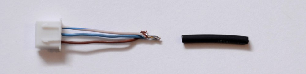
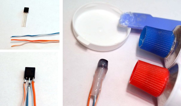
Buy DS18B20s chips. No matter what sensors are buying: cheap or at a high price. I've never seen "bad" DSes. Solder sensors to the wires and cover with two layers of 2-component epoxy resin as pictured below. It will work for years. White/orange - GND, white/blue - signal, orange - +5V.
For sensors at your compressor and discharge (+100 °C and higher) use heat-resistant sleeves at every wire.
To get precise temperature readings protect sensors against ambient air temperature influence with additional thermal insulation. Temperature readings from most of the sensors are interesting, but +/- few degrees does not matter. So, cover most of the sensors with thermal insulation as you wish.
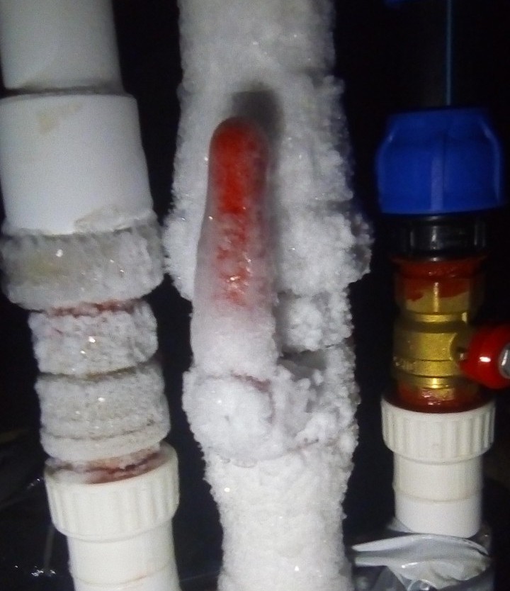
But two sensors "Before evaporator" and "After evaporator" are critical to EEV and needs an extra attention. The temperature of these sensors must be as close to the temperature of the copper tube as it possible. So, install Tae and Tbe sensors as pictured below. You can use thermal paste, but it is no significant difference with much more available silicone. Tape not shown at photos below, for clarity, but should be used with every insulation layer.
About water(glycol)<->refrigerant heat exchangers. You can use plate heat exchangers. Pros: the best efficiency. Cons: costs money. Potential oil return difficulties.
And oxygen brazing with (20%+)silver+copper solder required here:
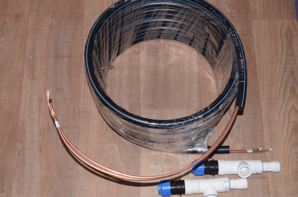
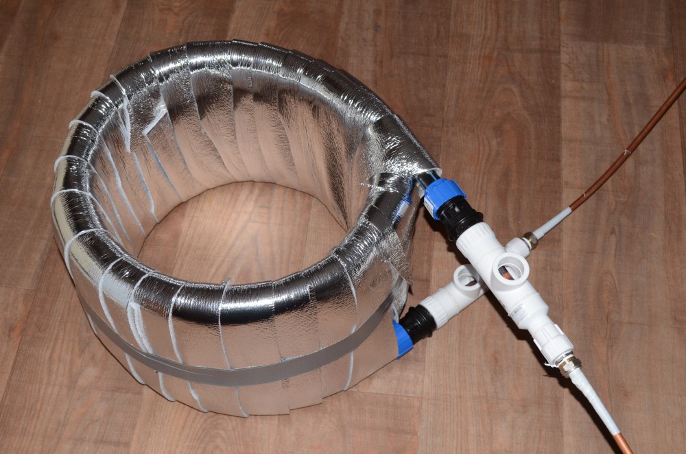
You can build your own "tube-in-tube" heat exchangers. It's not hard. Cheaper. The heat exchange efficiency is worse. No oil return problems. Very easy soldering. Heat exchanger math: 0.7..1.5 m2 of a copper tube per every 3kW of heat transfer.
Additionally, you can think "I'll take an old AC parts... Housing... Slightly change... An hour or two, day of work maximum and I'll get a refrigerant<->water heat exchanger in for a penny!". This idea is obvious. It was the first thing I've tried. You can try this, but to achieve "not very bad" performance it'll take more than a one day and much more than a few $$, even if you have unlimited access to older ACs.
Ok, I think that's enough for this appendix, this is a controller page, and not how-to-build-refrigeration-systems page.
Overall, your system with sensor locations will look like at a scheme below. Refrigerators (heat pumps) are simple devices.
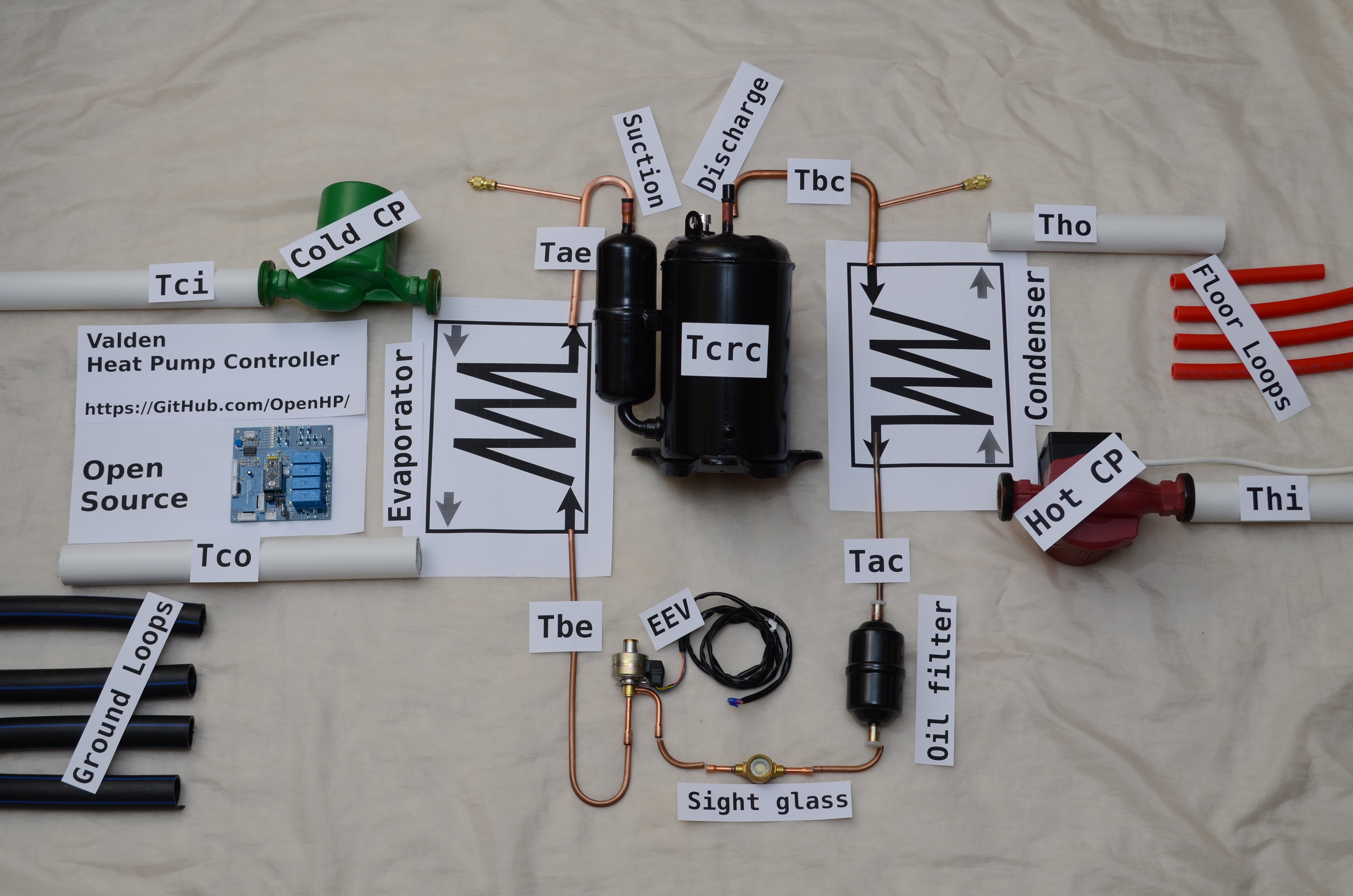
Your system works (or sleeps) depending on Thi temperature. For the end user it looks like setting up comfortable temperature of the warm floor via Remote Display.
## License
© 2018-2021 D.A.A. All rights reserved; gonzho AT web.de; https://github.com/openhp/HeatPumpController/ .
Text, media and other materials licensed under CC-BY-SA License v4.0 https://creativecommons.org/licenses/by-sa/4.0/ .
Attribution: You must clearly attribute Valden Heat Pump Controller ( https://github.com/openhp/HeatPumpController/ ) original work in any derivative works.
Share and Share Alike: If you make modifications or additions to the content you re-use, you must license them under the CC-BY-SA License v4.0 or later.
Indicate changes: If you make modifications or additions, you must indicate in a reasonable fashion that the original work has been modified.
You are free: to share and adapt the material for any purpose, even commercially, as long as you follow the license terms.
The firmware source code licensed under GPLv3 https://www.gnu.org/licenses/gpl-3.0.en.html .
This product is distributed in the hope that it will be useful, but WITHOUT ANY WARRANTY; without even the implied warranty of MERCHANTABILITY or FITNESS FOR A PARTICULAR PURPOSE. See the GNU General Public License for more details.
For third-party libraries licenses used in this product please refer to those libraries.
Further details, appendices, fine-tuning options, illustrations, abbreviations, and so on you can find in the permanent repository: https://github.com/openhp/HeatPumpController/.