0%
0%
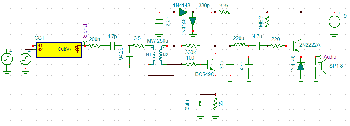
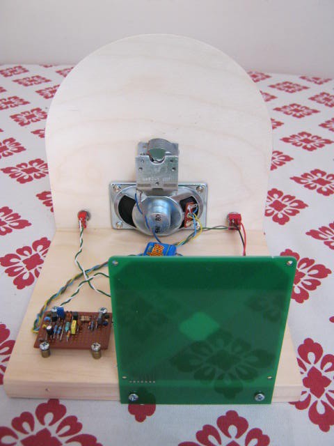
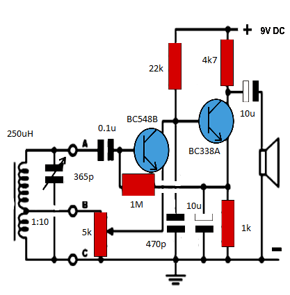
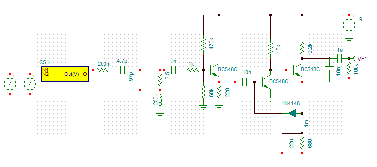
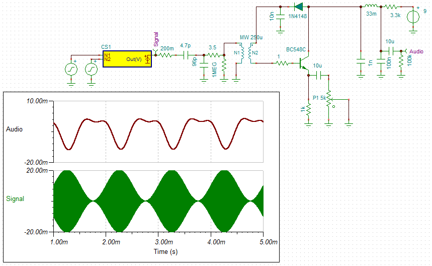
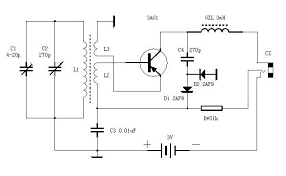
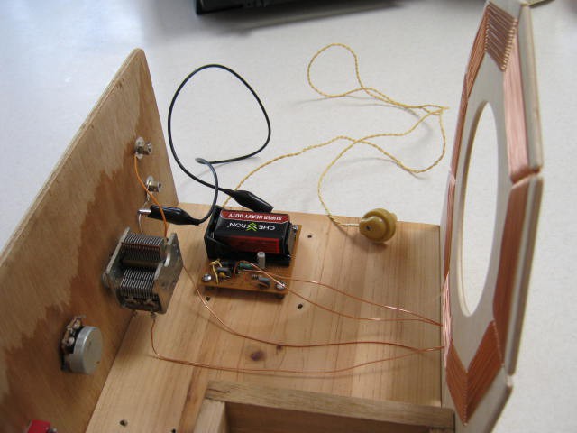
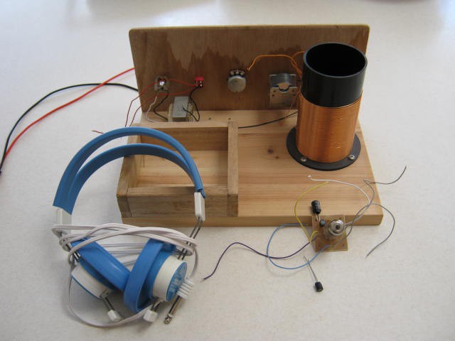
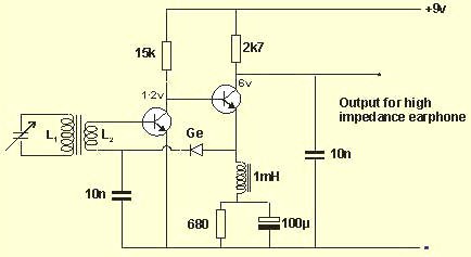
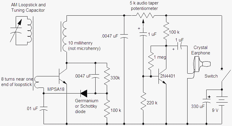
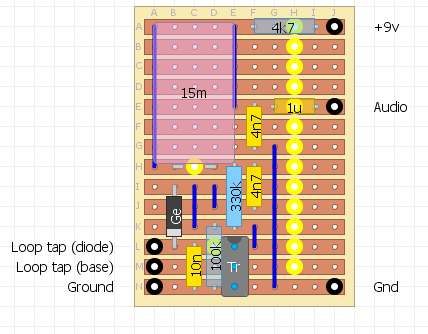
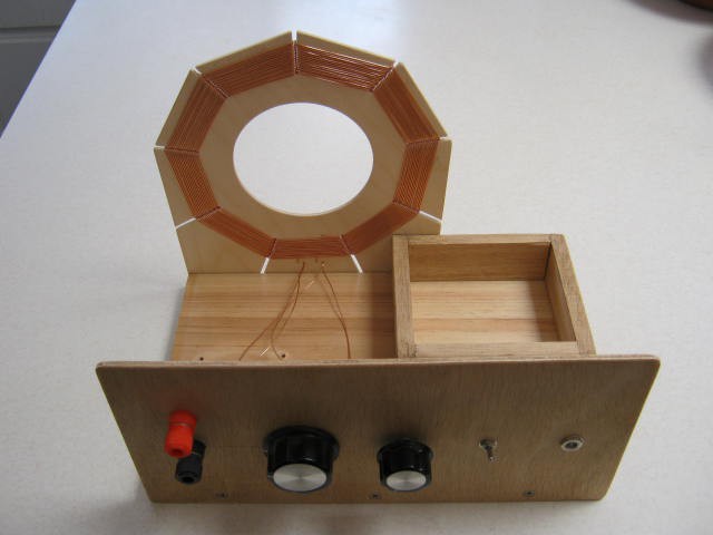
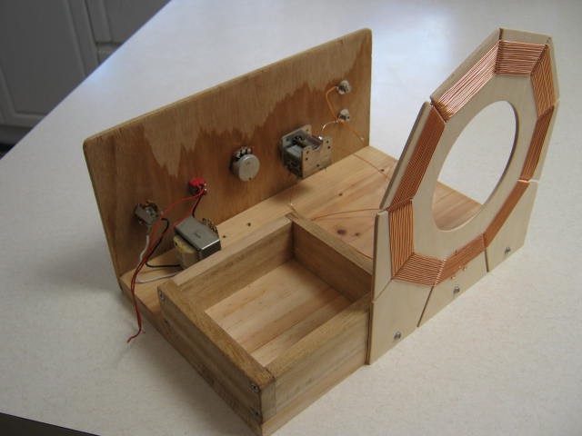
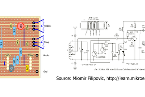
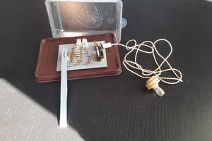
Super Simple MW/AM radio circuit
A one transistor MW/AM radio.
 agp.cooper
Become a Hackaday.io member
Already have an account? Log in.
Just one more thing
To make the experience fit your profile, pick a username and tell us what interests you.
Pick an awesome username
hackaday.io/
Your profile's URL: hackaday.io/username. Max 25 alphanumeric characters.
Pick a few interests
Projects that share your interests
People that share your interests


 Zach Armstrong
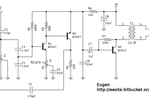
 Andrea Console
Hi AlanX
I have a question:
How perform first PNP one transistor reflex am receiver?
I see that you use general purpose BC548 and why you dont use
RF transistors like BF254 or N9018 or similar?