 agp.cooper
Reviving a Dead MW/AM Reflex Project
Long long ago
Long long ago I built a valve MW reflex receiver.
I could not get it to work so it went into the shed.
I can't remember how many years it has been in the shed.
Anyway with my revisit of MW receivers I pulled it out as a base for further experiments.
First I check the batteries and they were dead an I could not revive them.
Not a good idea to use sealed lead batteries in this type of project!
Next I saw that fake 15 mH choke (that is really a 15 uH choke).
Now the 15 mH choke was light on for this radio so 15 uH was the reason it did not work.
I had the ground and antenna hooked up the wrong way as well.
Anyway, no batteries so I pull it apart to try it out as a crystal set.
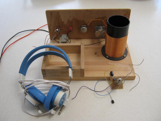
Here is the set in pieces:
And here is the fake 15mH next to a real one:
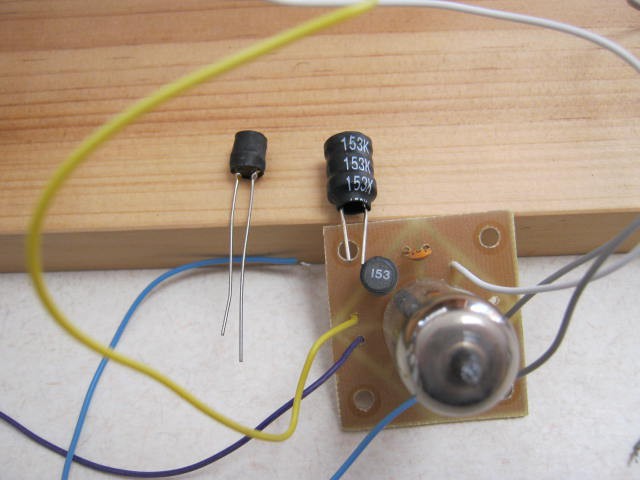
You can see that circuit board was made using a hacksaw to cut the copper foil!
Crystal Set
Anyway, I put up a 15 m long-wire aerial and a ground, added a Ge diode and listened for any MW stations using a crystal ear-piece.
Pretty poor. I could just detect a station on 720 kHz at the top end of the tuning range.
As the coil has not taps and the diode was across top of the coil the selectivity was dreadful.
So what was wrong?
First the coil is far from optimal with too much self-capacitance. The L/D is about 1.5 while the optimal L/D is about 0.5.
Second, the wire spacing should be about 1 to 1 not close wound as I have done.
Third, the black coil former is likely black as it has graphite in it, not good for Q.
And lastly no impedance taps for the diode.
So that coil will have to go.
Transistor Reflex
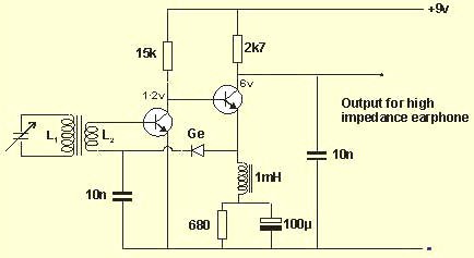
As a base for further experiments there is an old design I have used (long long ago) that works very well:
But I have gone with this one but less the audio amp:
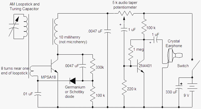
(source: http://www.techlib.com/electronics/reflex.htm)
The Ic is about 1.1 mA and the diode bias about 3 uA.
This author has a preference for aerial loops which I rather like.
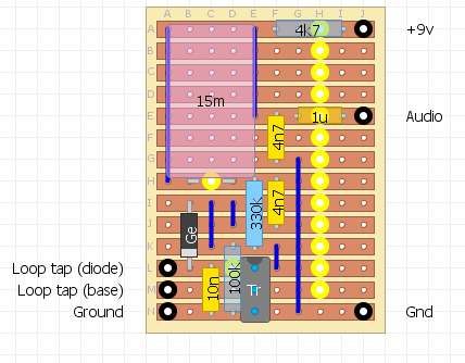
Here is the strip-board layout:
The new coil
After a bit of research I elected to build a spider coil.
I had 14 m of 1 mm diameter enamel coated copper wire (which I thought would be enough - wrong!).
I designed for 250 uH, here is the web after I ran out of wire (24 turns out of 37 turns):
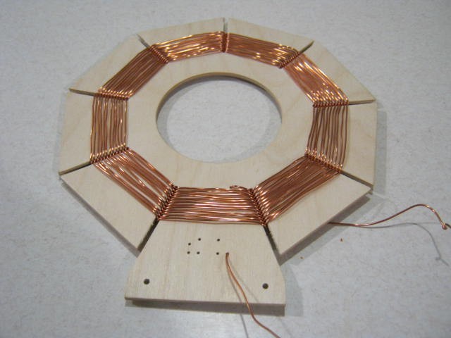
Two mistakes:
- 1 mm wire is a bit hard to handle, and
- the hole in the middle is just a fraction too small to put my hand through easily.
I will finish this design but the next one will use 0.8 mm wire.
The diameter of the coil frame is 200 mm (8 inches).
The design has 34 antenna turns and 3 coupling turns.
The new new coil
Too hard to get enough 1 mm diameter wire so I dropped down to 0.8 mm diameter wire and redesigned the coil.
Here is the finished coil:
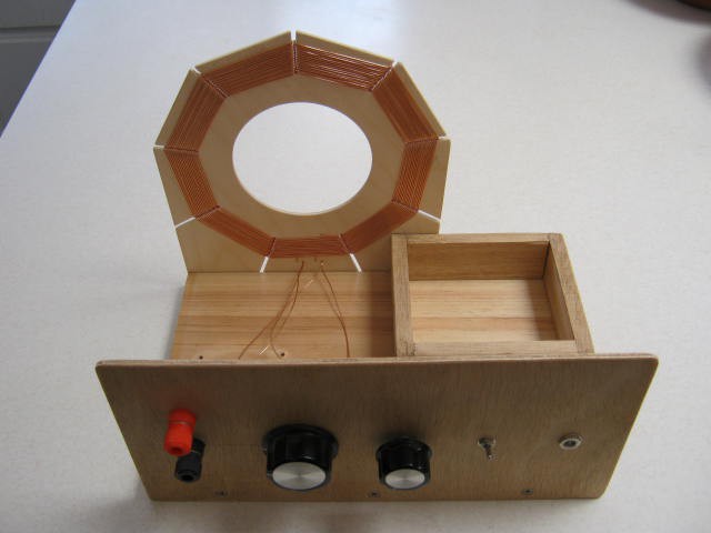
And another view:
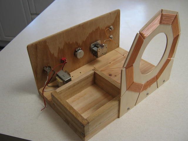
This coil is 32 turns total, 29 for the antenna coil and 3 for the coupling coil.
I was designed for a reflex set up.
I am staring to think the ratio 10:1 may be a bit extreme.
This was based on the design from http://www.techlib.com/electronics/reflex.htm.
It had 20 turns and 2 turns.
The problem with 10:1 is it is not much good for a crystal set.
Something like 2:1 or 3:1 would be better for a crystal set.
I can rewind the coupling coil to increase the turns later if needed.
As a crystal set this coil is just as bad as the first one due to over-loading by the diode and ear-piece.
It does not seem that reception of MW signals is not that great where I am located.
AlanX
Discussions
Become a Hackaday.io Member
Create an account to leave a comment. Already have an account? Log In.