 agp.cooper
Another MW Autodyne Receiver
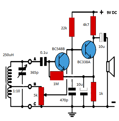
I knocked up this circuit as it claims so much (there is a version with a speaker transformer that claims loud speaker performance from two transistors) and is so simple:
![]()
The regeneration/gain control is a little strange (the gain will go down and then back up, as the regeneration feedback increases) but in practice it works very well.
Actually better than the reflex! The only strange thing was that from time to time it just stops by itself and I have to wind the regeneration to zero and back up again (or power off)?! It may be C4 playing games? The circuit probably needs a bypass capacitor from the collector of T2 to ground as well.
For transistors I just used the BC548B.
There is another version of this receiver with different component values:
http://www.homemade-circuits.com/2012/10/simplest-am-radio-receiver-with-speaker.html
I used his image but added the component values:
This circuit will work much better with an audio transformer.
The problem is that the audio transformers are the crappy small ones of the expensive (but still crappy) big ones.
So I decided to use a small potted AC transformer.
Found a PCB mount 0.3VA 220v to 18v job (equal to 1200 ohm to 8 ohm) that will be perfect for these radios for A$8/each.
The Reflex Receiver
I have been analysing this circuit and I am not that impressed (any more):

I should look at alternate biasing methods.
The Three Transistor Design
I am am now looking at this reflex:
The 33 mH choke is a bit of over the top, 1m works just as well.
I reworked the component values and got a big improvement in the simulator (x10):
A One Transistor Reflex
Modelling a one transistor reflex.
There are a number of schematics on the Internet.
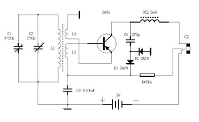
Here is a very simple one (the 636):
![]()
And a video from the Internet:
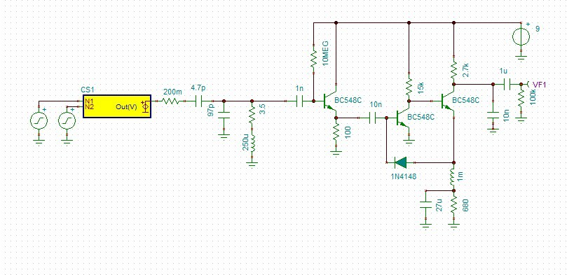
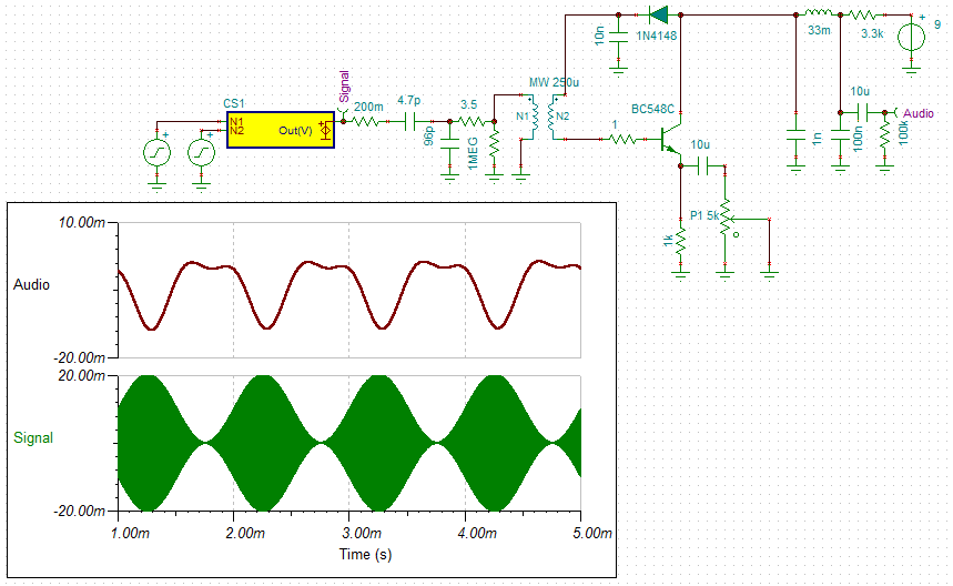
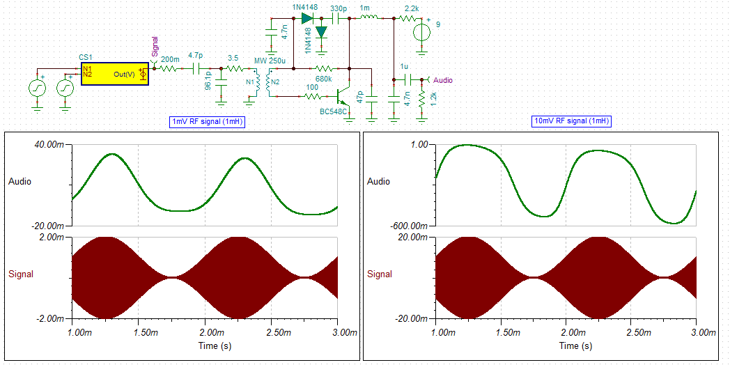
Here is my simulation of my version:
A number of changes were made:
- Modified for 9v and crystal ear-piece output.
- Added a 1k base resistor to stop "Colpitts oscillation".
The schematic consists of:
- On the far left, a the signal generator (before the the signal probe).
- Then the short wire antenna model.
- Then the tuning coil and tap at 10%.
- The the 636 circuit.
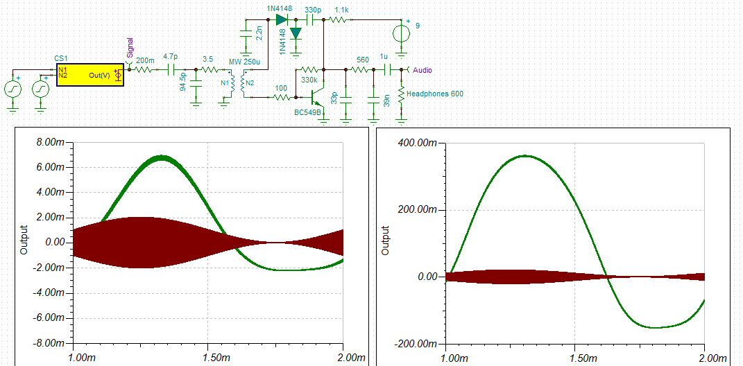
Analysis:
- The left analysis is of a 1 mv 1 Mhz signal modulated by a 1 Khz audio signal.
- The audio shows a square law distorted audio output of 6 mv (a gain of x3).
- The right analysis is of a 10 mv 1 Mhz signal modulated by a 1 Khz audio signal.
- The audio shows a square law distorted audio output of 900 mv (a gain of 45).
Replacing the 1 mH inductor with a 1k resistor, this reduced the gain by a factor of 3.
Increasing the tuning coil tap to 20% kills the tuning coil Q.
Here is another version that uses a higher coupling tap but uses regeneration (L3) to "fix" the Q (but L2 looks to be the wrong way?):
(source: http://electronicdesign.com/analog/rediscover-truly-tunable-hall-network)
More Optimisations on the 636 Reflex
Optimisations in a simulator can be false!
So the results should be reviewed to determine if they are reasonable.
I have had overly unrealistic performance from a simulator for my diode transistor NAND gates (at least 10x better than reality).
So I am getting very good improvements with the 636 reflex receiver but I think they are believable!
One thing I noticed with Rick Anderson's receiver above is that the 0.001uF capacitor from the collector of transistor 1 to ground was necessary.
At first I glance it appeared to be part of the low pass pi filter.
It was a little strange as it bypasses RF to ground in competition with the diode.
Reducing the value 10 fold improved performance (10 fold) but total removal killed the circuit?
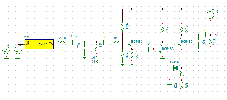
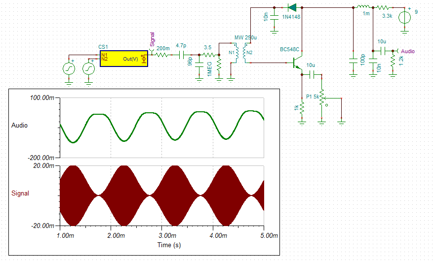
So I added this the the 636 reflex and got a huge improvement:
I also set the audio load to that of a transistor audio amplifier.
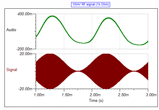
At higher signal levels (10mV RF) the audio is quite distorted.
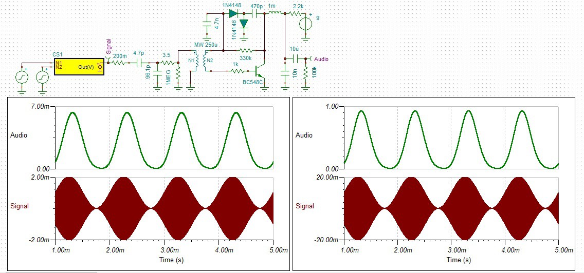
A higher audio load impedance helps:

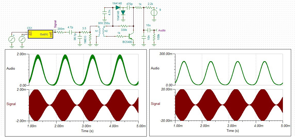
If you accept lower gain replacing the 1 mH choke with a 1k resistor also helps:
There is still some RF in the audio signal so a 4.7 nF bypass capacitor across the 1.2k audio load would help.
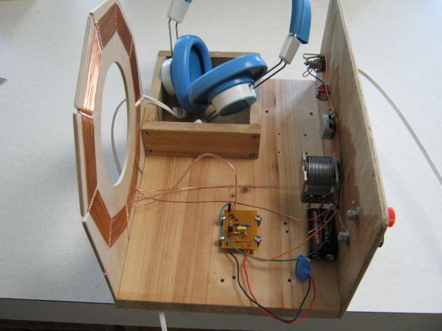
Here is the strip-board layout:

It Works
It works brilliantly!
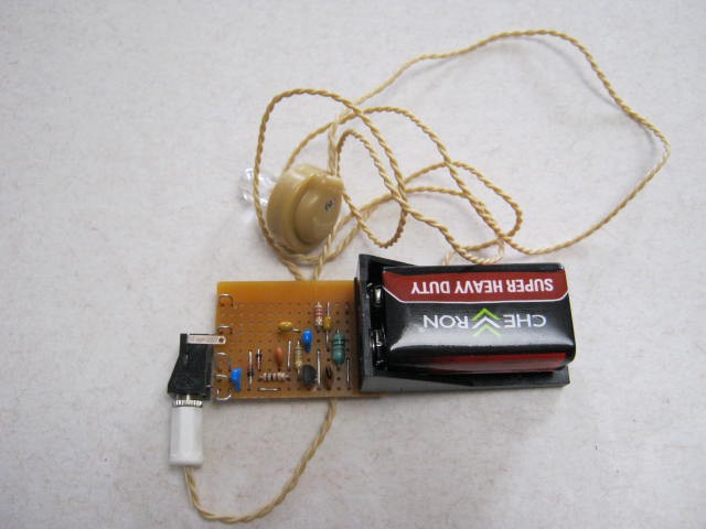
Actually it is too loud for my crystal ear-piece.
On the oscilloscope the audio was clipping at 3v pp!
When I powered it up I thought it was not working because I could not hear any static.
The transistor voltage checked out but I could not make it oscillate by touching it anywhere.
Attached the coupling coil connections (no antenna) and it amazed me.
The selectivity was not great but good enough (as per the simulation).
There is so much gain that a lower tap for greater selectivity would be of value else a regeneration coil.
This circuit with a speaker transformer would definitely work as a loud speaker radio.
Update
I have reworked the schematic for a 600 ohm set of headphones:
The current consumption is still only 3.2 mA.
I also swapped out the RF choke for a resistor (accepted the big gain drop!) and reduced the coupling coil turns from three to two, in order to increase the selectivity.
It works quite well (not as loud) but very selective (you get a surprise when with a small adjustment a station comes in quite strongly).
I have found all the Perth MW/AM stations (no antenna but I did have to rotate the set for the signal direction).
I will make up a new front panel for the receiver and bring this project to a close.
Here is the as built schematic:
If you really want some gain replace:
- the 1.1k resistor with a 3.3k resistor, and
- the 560 ohm resistor with a 220 uH RF choke.
You will need a volume control if you do this!
A Transistor Speaker Driver
In theory a Class B amplifier should work fine for this receiver. Here is my design:
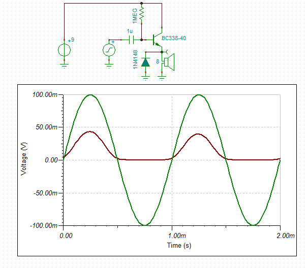
The base resistor was chosen for a quiescent current is about 1mA.
The value depends on the transistor type so check you circuit in operation.
The diode recirculates and inductive currents from the speaker (not really necessary).
The input impedance is between 5k and 15k depending on the transistor gain.
Testing the Audio Amplifier
Bread-boarded the design and it "motorboated" (i.e. sounds like a "motorboat").
The usual diagnosis for this is audio feedback through the power supply.
Okay, add a 120R resistor and a 100uF capacitor to the power supply. No.
Noted that hand capacitance influenced/stopped the motorboat.
So it must be RF feedback. Added a 220R resistor to the transistor base and all good.
The quiescent current was about 2 mA using a 1 M bias resistor and a 2N2222A.
I used the 2N2222A as I have a heap and they are rated at 500 mA DC.

I have made three other changes:
- Reduced the power supply to 3v (reduces gain)
- Linked the transformer as a single tapped coil (reduces gain?)
- Add a gain switch (for strong stations) but a variable 100R potentiometer (if you can get one) would work better.
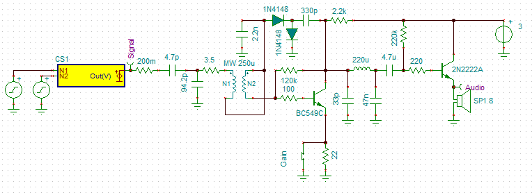
Because of the gain reductions the RF choke version may be a better circuit to use:
Printed Circuit MW Coil
Winding coils is not as exciting as it used to be!
Here is a printed circuit board MW coil:
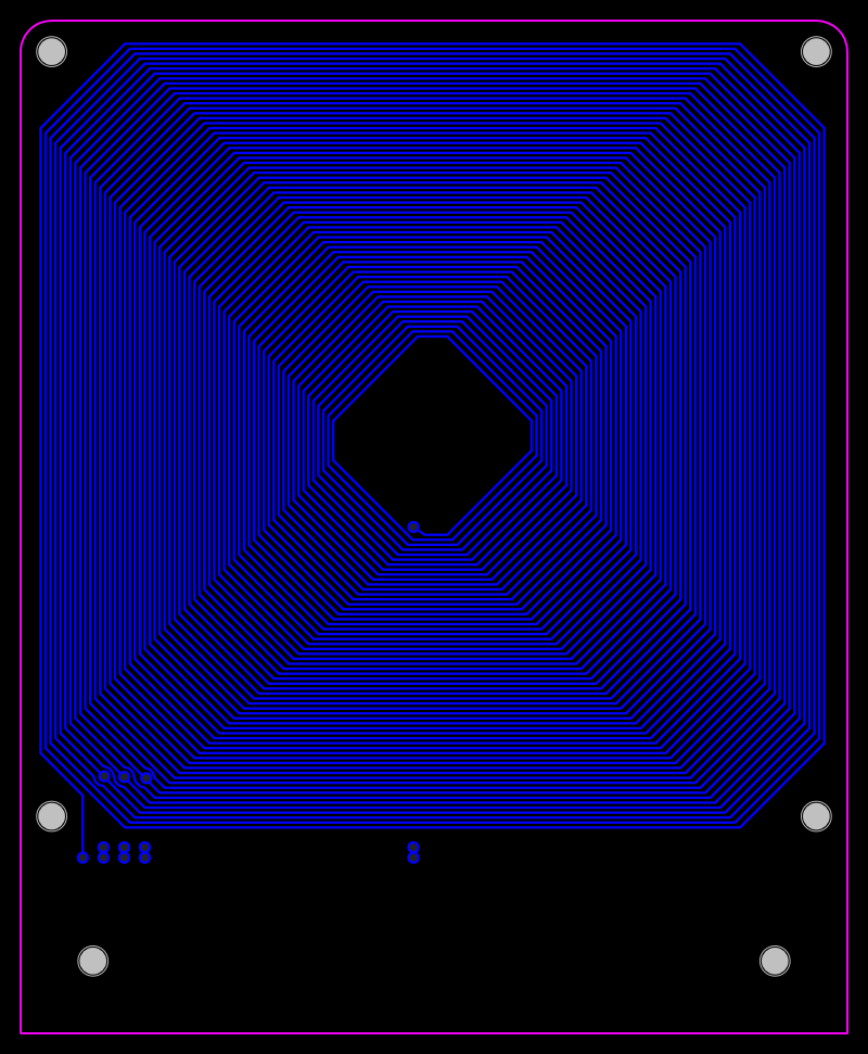
The coil is single sided and has 64 turns total. Taps at 4, 6 and 8 turns:
- Inductance is about 224 uH for 64 turns and the Q a low 38 for 1 oz copper PCB.
- Self resonant frequency of 1.75 MHz.
- If the coil is ground at the 8th turn then the coupling turns can be 2, 4 or 8 turns to 56 turns (163 uH).
- If the coil is ground at the 6th turn then the coupling turns can be 2 or 6 turns to 58 turns (177 uH).
- If the coil is ground at the 4th turn then the inductance is 192 uH.
Increasing the copper weight (2 oz) costs but the Q increases to 58.
AlanX
Discussions
Become a Hackaday.io Member
Create an account to leave a comment. Already have an account? Log In.