 Aspiring Roboticist
Overview
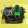
This project has two units, a sensor unit and a controller unit. The sensor unit consists of a Raspberry Pi Zero W and an Adafruit BNO055 9 degree of free
dom IMU Board. The controller unit consists of another Pi Zero W and a Pololu Maestro Servo Controller.
The project has two units: the sensor unit and the controller unit. The Sensor unit consists of a Raspberry Pi Zero W and an Adafruit BNO055 9-Degrees of Freedom IMU board. The controller unit consists of another Pi Zero W and a Pololu Maestro Servo Controller. The two communicate with each other using XMLRPC running over WiFi. The Sensor unit acts as the server and the Controller unit acts as the client.
I mounted the sensor Pi and IMU board on the brim of a baseball cap, so it will track my head movements.
The code for the project is open source, of course, and posted on GitHub.
How it Works
The IMU board has a triaxial accelerometer, a triaxial gyroscope, and a triaxial magnetometer. The magnetometer provides orientation relative to magnetic north and is not used in the IMU only mode used in this project, as only relative orientation to the starting position (which should be looking straight forward and level) is desired. The accelerometers and gyroscope. The secret sauce in this board is that it includes a high speed ARM Cortex-M0 based processor that takes in the raw data from all the sensors, fuses it, and outputs the calculated orientation in real-time.
The orientation is provided as Euler angles (think roll, pitch, yaw rotations about the board’s x, y, and z axes), as the x, y, and z components of the gravitational force vector, or as a quaternion (which defines the direction of a single rotation axis and the amount of rotation about that axis). Unfortunately the chip has some flaws in calculating Euler angles, so it’s safer to use the quaternion output. For this project, the aviation convention is used for angles (x axis looking forward, y axis pointing right, and z axis down). Note however, that some of the servos move in the opposite direction, so you’ll see some sign changes in the function that converts the angles to actual servo commands).
For moving the skull, we want the Euler angles, though, to command the tilt, nod, and turn servos of the skull. Fortunately it’s easy to find the math to implement to convert the quaternion value provided into the proper Euler angles.
In this project, the sensor Pi is set up to be an XMLRPC server which, when receiving the appropriate XMLRPC request, queries the board for the current orientation, provided as a quaternion, and wirelessly sends this to the controller Pi that made the request.
The controller Pi makes this request 50 times per second. Once it has the quaternion, it converts it to the three Euler angles, and then converts each angle into the appropriate servo command to pass on to the maestro.py module that communicates with the Maestro servo controller. In addition, there is a subroutine that sends commands to move the eyes servo in a pre-determined, but relatively random, fashion.
This video () shows the system in action. The goal is not to get perfectly synchronized motion between the operator and the skull, as the servos will always introduce significant delay. Rather, the intent is to generate spontaneous and realistic movements by capturing the motion of the operator, who normally will be out of sight.
Software Prerequisites
The sensor software uses CircuitPython and Adafruit’s Blinka library must be installed to support CircuitPython on a Pi. In addition, the adafruit_bno055 program is needed to interface with the board. Be sure to use the CircuitPython version rather than the earlier version.
Hardware
This project requires two Raspberry Pi’s with WiFi (I used Pi Zero W’s), an Adafruit BNO055 IMU board, and a Pololu Maestro Servo...
Read more »
 Ranjib Dey
 Tobius
 durapensa
Sweet but also… where did you get that super good looking Skeleton?