So what am I trying to do here? This project will investigate switch-mode power supplies (SMPS) with a transformer. This isn't a single-ended topology like a flyback, it is push-pull. Sort of like a class A-B audio amplifier. Maybe class D. A transformer SMPS has several advantages over a single-ended topology: Smaller magnetics, low noise, no core gap, etc. It does require a more complex PWM driver circuit. Maybe when working, this will be a voltage booster to convert 6V to 90V for an antique radio project. For now, it's just an experimental power supply project.
PWM output signals drive the switching transistors, BJT or MOSFET. For a transformer based power supply, 2 phases are needed. The drive phases can never overlap, because that would short the transformer primary. PWM duty should vary from 0-49% for each phase. The drive phases should be balanced and separated by 180 degrees.
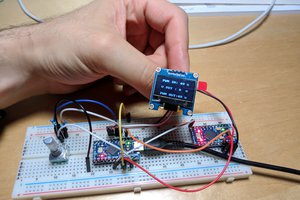
There are some ICs available, but they are specialized and not what I want. An arduino compatible pro-mini should be able to generate the PWM driver signals. Since the PWM has to stay balanced, it would be best to generate the PWM using a timer peripheral on the chip. A software timed solution might not work well. Hopefully, ADC and software can be used for the feedback loop.
Reference info
https://www.analog.com/media/en/technical-documentation/application-notes/AN118fb.pdf A classic Jim Williams app note. Lots of info about Royer converters and low noise technique. Some IC stuff, but nothing about microcontrollers.
https://www.ti.com/product/SN6505A TI has an interesting driver chip with integrated MOSFETs. It's open loop and requires a secondary regulator. Max input voltage is only 5.5V. Close, but I wanted 8V max.
https://www.analog.com/en/products/lt3999.html Analog Devices has a monolithic chip that might work for this application. It's in a 3x3mm lead-less package, so that's not DIY friendly.
 Dave
Dave
 Daphne
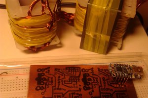
 Louis H