 Justin Skists
Yes, I thought that I might enter the RetroChallenge 2021/10.
The Jupiter ACE has always fascinated me; a machine created in the early 80’s. It used an implementation of Forth, for its “operating system”, rather than the much more common BASIC.
It’s a machine that I’ll probably never own. So, why not recreate it in the form of the RC2014? Why not create/adapt add-ons to allow the RC2014 to run the Jupiter ACE ROM image unmodified?
Yes, it’s easy enough to run a Jupiter ACE in an emulator, on a Raspberry PI, but where is the fun in that? I want to learn how the 80’s computer worked! I’m a software engineer, by trade, so hardware design is quite unknown to me…
I perfectly accept that this probably is not very challenging, to most. Personally, I think that real challenge is, for me, to actually finish something…

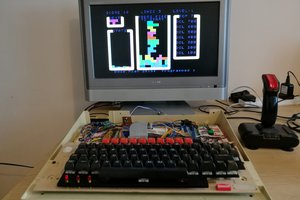
 6502Nerd
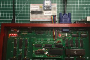
 Marcel van Kervinck
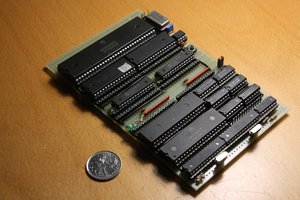
 Hayden Kroepfl
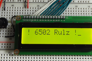
 Jim Jagielski