IN, OUT, IN, OUT, shake it all about!
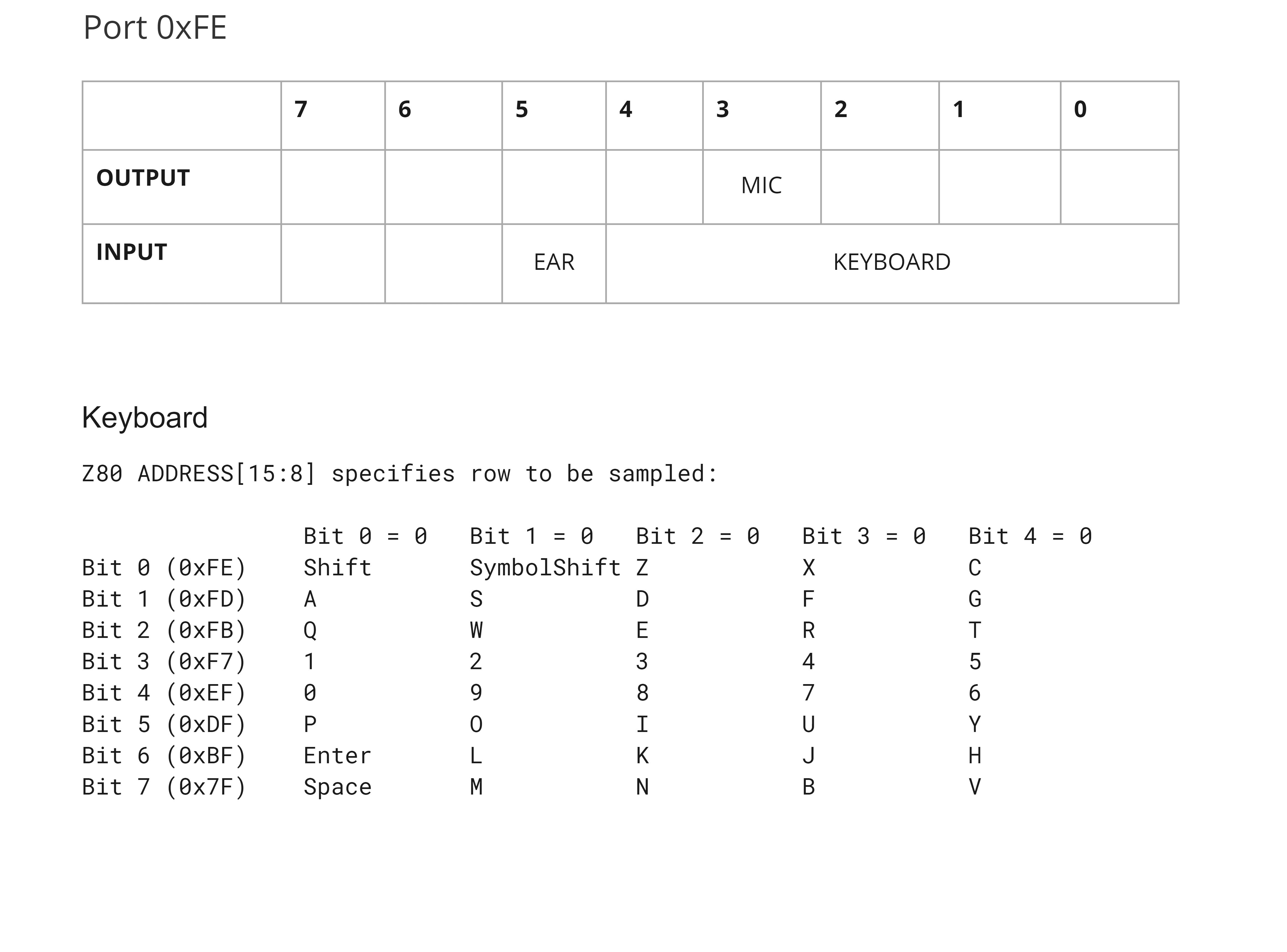
According to this IO document, there is only one official Z80 port used, at 0xFE. Actually, if you look at the schematics, only ADDRESS[0] is decoded...so, any even address would trigger it!
Output
On an OUT instruction to to 0xFE, only BIT[3] is really used; the MIC. This, assumably, would send high/low signals to the tape recorder to save files.
Input
The input of port 0xFE is a little more interesting:

BIT[5] is the current level of the incoming tape signal for loading from the tape.
BIT[4:0] is a sampling of the keyboard matrix. The current row is selected using the Z80 ADDRESS[15:8] during the IN instruction read.
There is plenty of spare bits in the port for future use. For example, the ZX Spectrum uses BIT[4] on the output for speaker control, and BIT[2:0] for border colour...
Speaker
So, what about the speaker? The Jupiter ACE had a speaker, and it needs to be controlled. Shouldn't there be a BIT in the 0xFE port assigned to it?
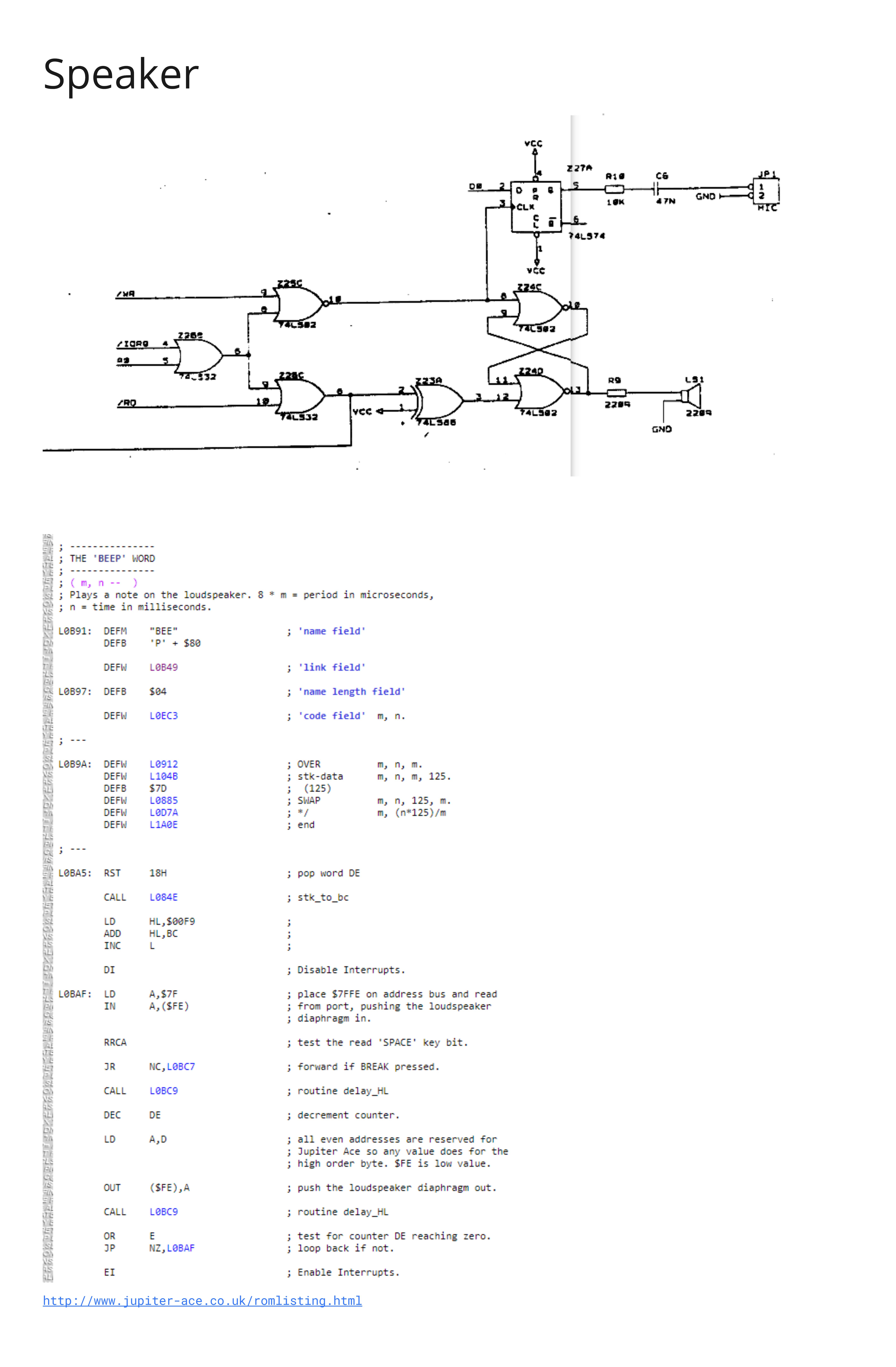
Well, looking at the schematics, there is a flip-flop used in the speaker. Why? Well, think about how a speaker diaphram works, to make sound: in, out, in, out, in, out...
Looking at the schematics, any write to 0xFE pushes the speaker's diaphragm out, and any read from 0xFE pulls the diaphragm in. IN, OUT, IN, OUT....
The Jupiter ACE ROM listing seems to confirm it, with the BEEP word.

 Justin Skists
Discussions
Become a Hackaday.io Member
Create an account to leave a comment. Already have an account? Log In.