 Justin Skists
How does it work, again?
As I mentioned before, the Jupiter ACE exercised its beeping-speaker by reading and writing to the I/O port. Any write to the I/O port pushes the speaker diaphram out, and any read pulls it in.
The ZX Spectrum uses bit 4 of the I/O port to write to the beeper. So using ACE's technique, we can save a bit in the 8-bit output port, But, considering only one bit is used anyway, it's not much of a saving!
The downside of ACE's speaker circuitry, is that you'd presumably get an intermittent and random clicking sound during the operation.
Implementation
Well, the original schematics of the Jupiter ACE uses a flip-flop to interface with the speaker. So, basically, a write to the I/O port sets the flip-flop, and a read resets it.
We could add a 74LS74 chip, and NOT the decoded RD and WR signals. But there is a different trick that we can use.
Microchip's PIC16F1509, that I've chosen for my design (because I had one lying around) has something known as a Configurable Logic Cell. It's a neat little peripheral that can combine other peripherals together, along with CPU control, to implement hardware-based protocols. For example, you could combine a signal with a 38KHz timer for infrared transmission.
CLCs are not as flexible as a CPLD, and they are restricted to which pins can be used, but they can have their uses.
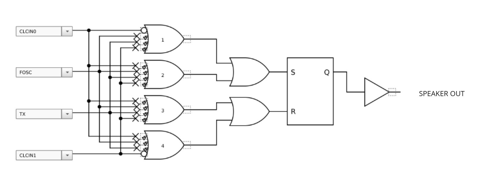
And for our use, we'll just need to implement a flip-flip. Well, set up a CLC to use a flip-flop and invert the inputs.
Something like this:
Discussions
Become a Hackaday.io Member
Create an account to leave a comment. Already have an account? Log In.