 Swaleh Owais
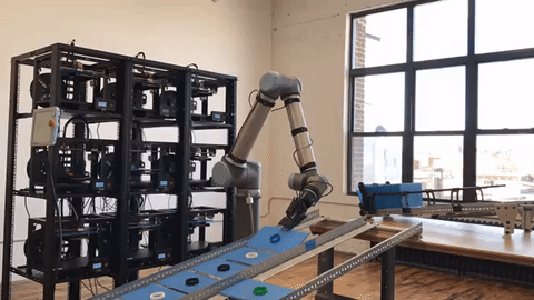
Demo Video
**NOTE: If you are hoping to get a quick overview of this project, please watch this brief two minute video.**
[Figure 1: Robot Demo Video]
Background
The Problem with Traditional Manufacturing
Traditional manufacturing involves developing custom machinery that is perfectly optimized to mass produce a specific part. Examples of such machines include injection molds, vacuum formers, and die presses. While building custom machinery is extremely expensive, the costs are recouped after millions of parts are produced. But what happens if manufacturers do not want to produce millions of parts?
Unfortunately, the high initial costs to set up a manufacturing line inhibits companies, specifically startups and Small Medium Enterprises (SMEs), from running smaller production batches. In addition to the large expenses, there are also long lead times required to set up a production line. Both of these factors discourage companies from updating/modifying a part’s design once the production line is finished. Ideally, a manufacturing engineer should be able to iterate on designs as often and as easily as a software engineer.
The Potential of 3D Printing Farms
A 3D printing farm is a facility that contains a large fleet of 3D printers which work together to mass produce parts. With custom software, these 3D printers are networked together to process print jobs; similar to the way servers in a server farm are networked together to process data. A 3D printer is the polar opposite of the custom machines used in traditional factories. A custom machine is precisely designed to manufacture a specific part, while a 3D printer can print a part of any geometry; albeit not very efficiently. At scale, it will always be more economical to use a custom machine instead of a 3D printer to manufacture parts. However, 3D printers have several advantages that make them preferable for low volume production. A 3D printer can start printing parts as soon as it receives that part’s digital CAD file. On the other hand, traditional factories require a large initial lead time to start manufacturing new parts. It takes a long time to design, build, and deploy the required custom machinery. It is important to note that once a custom machine is built, like an injection mold or die press, it will produce parts exponentially quicker than a 3D printer. However, if we factor in the lead time required to build the custom machines, the 3D printers will be optimal up to a certain number of parts. This niche is the area of production between prototyping and mass production.
Since a 3D printer can instantly switch between manufacturing different parts, manufactures can update/refine a part’s design as they wish. This enables a part to have more iteration cycles and for the manufacturer to be respond quickly to market demands. Essentially, a 3D printer allows a manufacturing engineer to adopt the agile design ideology[of a software engineer. Moreover, 3D printing allows manufacturers to explore areas like mass customization. For example, instead of a company producing 1000 identical shoe soles with an injection mold, they can 3D print 1000 unique shoe soles that are each customized to fit a specific person. From a 3D printing perspective, it takes as much time to print 1000 copies of the same part as it does to print 1000 unique parts (of roughly the same size).
Making 3D Printer Farms more Efficient with Automation
Before we get carried away by the potential of 3D printing, it is important to acknowledge that the manufacturing capacity of a 3D printer farm that contains hundreds of 3D printers is still dwarfed by a traditional factory. Therefore, it is vital that we explore every way that we can improve the efficiency of a 3D printer farm. One obvious avenue is automation. A key bottleneck in 3D printer farms is the requirement of human labour to start/remove print jobs from the machine. By developing some sort of robotic solution to perform this task, we can drastically increase the production capacity of a 3D printer farm.
Project Scope and Prior Art
The purpose of this project is to build a robot that automates 3D printers. Specifically, the robot should be able to remove finished print jobs from 3D printers and start new ones. With our robot, a 3D printer farm should be able to output a continuous stream of print jobs without any need for human assistance.
Due to the discussed advantages of automating a 3D printer farm, multiple companies have already attempted to build a robot that performs this task. As part of our background research, we examined two existing robotic solutions built by Voodoo Manufacturing® and Formlabs® respectively.
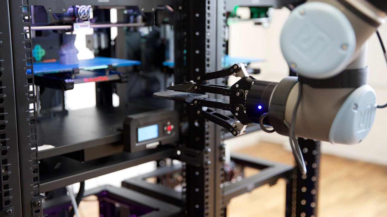
In 2015, Voodoo Manufacturing® demonstrated Project Skywalker: an autonomous 3D Printing Factory. The factory features a 3x3 array of 3D printers tended to by a 6 axis industrial robot arm. This project is the first publicly documented attempt at 3D printer machine tending. While Voodoo Manufacturing® showed the utility of automating 3D printers, we felt their design solution was over engineered. This is evident by the fact their industrial robot arm costs more than the sum total of all the 3D printers used in the factory (UR-10e Robot Arm: ~$40,000; 9 Makerbot Replicator 2 3D Printers: ~$18,000). Our team believes that a much simpler and cheaper robot could be built internally and still accomplish the same task.
[Figure 2: Autonomous Printing Cell developed by Voodoo Manufacturing]
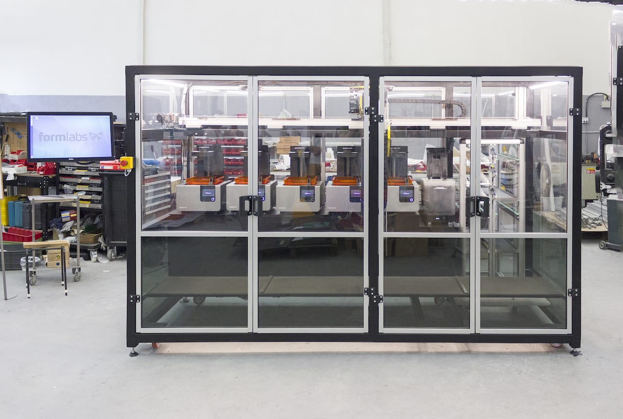
In 2017, Formlabs® released the Form Cell™: an automated 3D printing solution. The Form Cell™ contains several 3D printers, each of which are tended to by a SCARA robot mounted on a gantry system. The Form Cell™ is currently in use by many dentures and prosthetics manufacturers. The Form Cell™ is closer to the robotic solution that our team would like to build. Like Formlabs®, we will also develop a robot internally for performing 3D printer machine tending. However, we disagree with Formlabs® decision to mount the robot arm that tends to the 3D printers on a gantry system. Instead, we believe that such a robot arm should be mounted on a mobile base. This configuration would greatly reduce the footprint of the system. Moreover, a mobile base can easily transverse an entire room, while a gantry system can only move along a set 2D plane. In the latter configuration, users have less versatility in repositioning and adding 3D printers to the factory. This goes against our project’s goal of developing a flexible manufacturing facility.
While Voodoo Manufacturing® and Formlabs® succeeded in automating 3D printing production, neither of their solutions met our goal of a flexible, lean, and agile manufacturing option. Both of the above solutions require upfront costs that are too high for most SMEs. Moreover, both designs have extremely large footprints. The autonomous component more than doubles the size of the printer farm. Most importantly, the design solutions are similar to traditional manufacturing cells in that they are not easy for users to adjust, modify, and expand after installation.
To ensure our design solution addresses the problems of previous automated 3D Printer Farms, we explored other robotic systems that were relevant to our project. In particular, we discussed different end effector options for our design. Previous 3D printer Farm robots used simple parallel arm grippers to manipulate build plates.
These grippers require a high degree of accuracy to consistently pick up build plates. A better alternative would be a magnetic gripper system, similar to ones used in the automotive industry. Magnetic grippers would allow for higher tolerance when manipulating the steel build plates.
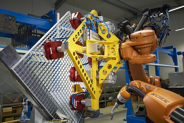
[Figure 5: Automotive component manipulated by a magnetic gripper]
Concept Generation and Decision Making
In total, this project has three main components: 1. A fleet of 3D printers connected together in a network, 2. A robot that tends to all 3D printers connected to the network, 3. A software application that allows users to remotely control and interact with the printer farm.
Among these three components, the mechanical design challenge is to develop a mechanism that autonomously ejects print jobs from 3D printers. To solve this challenge, we researched and explored many potential solutions. We built functional prototypes for solutions that were likely to succeed. Figure 6 below outlines a decision matrix of our top six design solutions. Our team did not not include safety as a criterion in the decision matrix because none of the design solutions posed any considerable hazard/risk.

[Figure 6: Decision Matrix for 3D Printer Automation Design]
The following is a list of qualitative and quantitative design criteria that the team came up with to determine the best design concept from our list of potential design concepts found in the next section:

Wheeled Printer Tending Robot

[Figure 7: Wheeled Printer Robot Design]
The wheeled printer robot design makes use of an omni-directional drive system and winch sub assembly to pick up the build surface from a 3D printer. The build surface is modified to allow the prongs of the robot to slide in and the slider motor pulls a cable to lift the winch sub assembly and prongs upward to remove the build surface with the print. The robot then navigates using the omni-directional drive and places the surface for storage and places a fresh surface on the printer.
Magnetic Build Surface Roller

[Figure 8: Magnetic Build Surface Design]
The magnetic build surface roller is a modification directly onto the printer build plate. A servo motor controls a blunt wedge to roll underneath a magnetic build surface to pop the print off the top. The opposite side of the wedge is flat and will knock the print off the bed when returning to the starting position. This clears the bed of the print and the printer can start the next print.
Plastic Sheet Printer
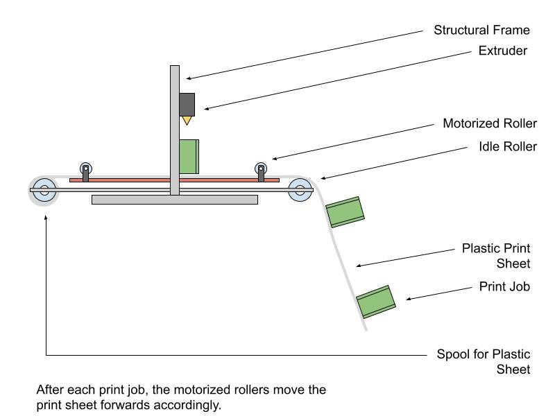
[Figure 9: Plastic Sheet Printer Design]
In this design, a long plastic sheet is laid over a 3D printer’s build plates. The machine prints on top of this plastic sheet. After each print job is completed, the motorized rollers move the plastic sheet forwards. The machine then completes the next print job on the newly exposed section of the plastic sheet. Most of the plastic sheet is stored on a winch mounted to the back of the 3D printer.
Railed Gantry Printer Robot
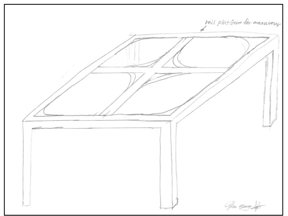
[Figure 10: Railed Gantry Printer Design]
The railed gantry system suspends the 3-D printer above a massive print space. The 3-D printer moves around through a monorail system that is modular and capable of expanding the printing space if needed. The system is a possible solution to the problem statement since the system would expand the printing space to a point that multiple sets of print jobs can be done within the space before the machine requiring attendance.
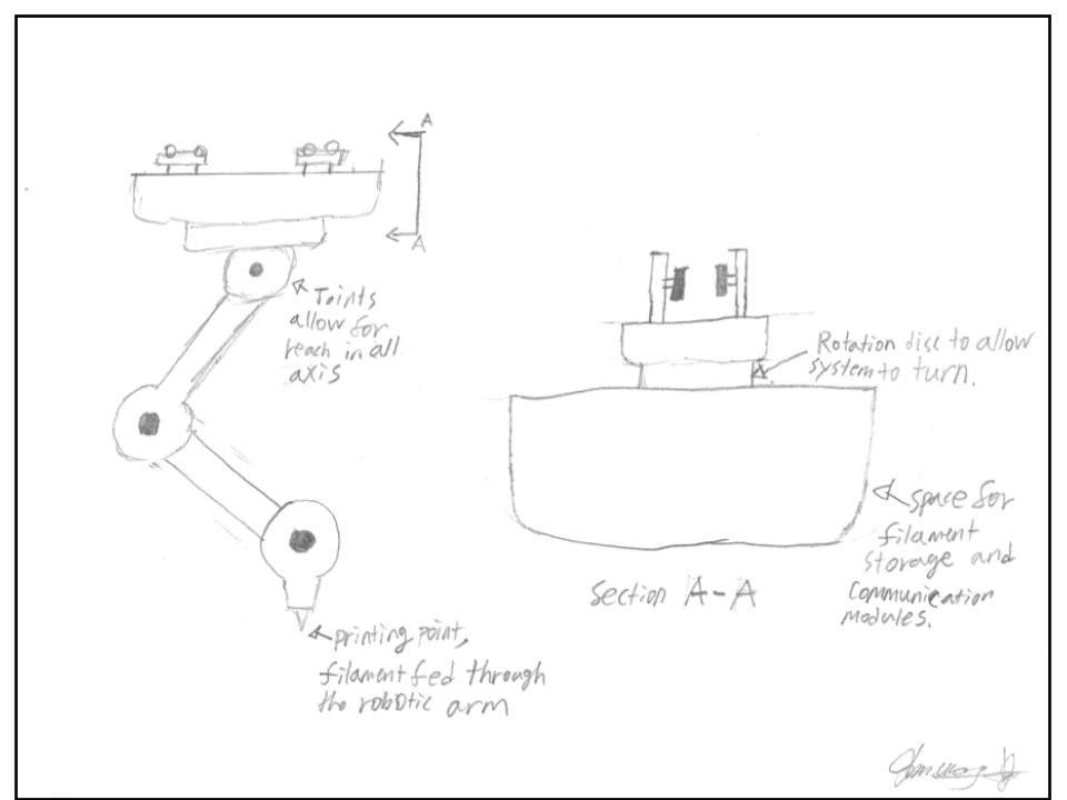
Stationary 5 Axis Robotic Arm

[Figure 11: Stationary 5-Axis Robot Design]
The stationary 5-axis robotic arm design is like a gantry robot with a modified wrist end effector. Once a print is complete on the build surface the wedge end effector is employed to pry it off the print bed. After the print is off the bed, the first revolute joint is used to swing the end effector across the surface to knock the print off and clear the print bed to start a new print.
Initial Design Investigation
After analyzing the decision matrix discussed in Concept Generation and Decision Making, our team selected the Wheeled Printer Robot design concept. We felt this idea effectively met out design goal of automating a 3D printing farm.
After selecting the Wheeler Printer Robot design idea, we decided that this robot’s specific function would be swapping build plates on 3D Printers in the farm. We chose to mount this robot on a mobile base or Automated Guided Vehicle (AGV) so that the completed robot could easily tend to a large number of 3D printers. A simulation of how this system works is shown below.

[Figure 12: Simulation of Robot Operation - https://youtu.be/IREE1Wb3AgE]
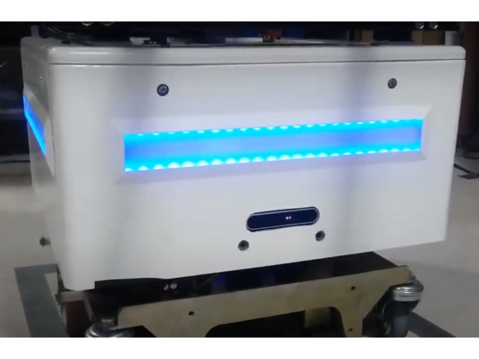
As shown in the demo video below, our machine has a simple but effective design for both the end effectors and lift system. The end effector uses electromagnets to remove the metal build plates from the 3D printers. The lift system is a motorized winch that raises/lowers the end effector.

[Figure 13: Demo of Prototype - https://youtu.be/kJlQVXltS90]
While designing our current prototype, we used K&J Magnetics simulation toolkit to determine the magnetic force connecting the steel build plate to the 3D printer. We found the total force to be 103.88 lbf. Unfortunately, our electromagnetic end effector only exerted 66.92 lbf. To reduce the magnetic force between the build plate and 3D printer, we placed an aluminum plate between the two objects.
While designing our current prototype, we used K&J Magnetics simulation toolkit to determine the magnetic force connecting the steel build plate to the 3D printer. We found the total force to be 103.88 lbf. Unfortunately, our electromagnetic end effector only exerted 66.92 lbf. To reduce the magnetic force between the build plate and 3D printer, we placed an aluminum plate between the two objects.
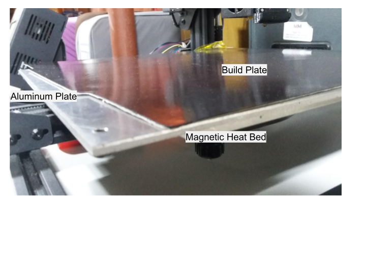
[Figure 14: Aluminum Plate used to Reduce Magnetic Field]
We optimized the thickness of this aluminum plate using Coulomb’s law, as shown in (1). After assuming a permeability of 1.256665 10−6 H/m, we found that a ⅛ in aluminum plate would reduce the magnetic force between the build plate and 3D printer to approximately 46 lbf.
|
(5, 1) |

After inserting the ⅛ in aluminum plate, the magnetic end effector was able to successfully lift the build plate.
Our team deliberated between using various aluminum extrusion profiles for the frame of the prototype. Specifically, we compared the following three profiles.
[Table 1: Material Properties of Aluminum Extrusions]
Profile (mm) | 20x20 | 30x30 | 40x40 |
Cross Sectional Area (mm^2) | 162.21 | 349.54 | 842.11 |
Max Stress (PSI) | 35535.2 | 35534.2 | 35534.2 |
We preferred to use the smallest aluminum profile to keep the robot as lightweight as possible. The maximum force acting on the robot frame is 46 lbf. Using (2), we verified that the stress experienced by the end effector was far less than the maximum allowable shear stress.
|
(6, 2) |

Final Prototype Features and Project Completion
We have successfully built a mobile robot that can automatically eject print jobs from 3D printers. As shown in the demo video, the robot can effectively navigate to various 3D printers and perform basic machine tending (removal and replacement of build plates). More details about each of the robot's key features are detailed below.
[Figure 15: Project Demo Video]
Electromagnetic End Effector
The robot uses an electromagnetic end effector to manipulate the 3D printers' steel build plates. The end effector contains four of these which align with the edges of a standard 220mm build plate. Together these magnets induce over 60 lbf on the build plate, which is an adequate amount of force to consistently dislodge and move the plate. Demonstrations of the end effector are shown in the below gifs.
[Figure 16: Testing electromagnets]
[Figure 17: Lifting Build Plate]
[Figure 18: Using End Effector to Lift Build Plate]
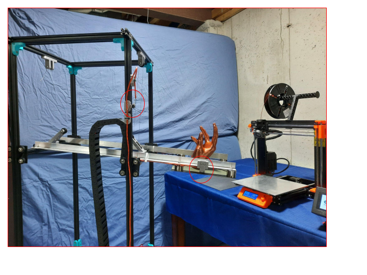
Winch Lift System
The robot has a pulley lift system that raises and lowers the end effector. The total range of the lift system is 900 mm. Either end of the lift system has a limit switch that acts as an endstop.
[Figure 19: Full Range of Lift System]
[Figure 20: Robot dropping off a finished print job]

[Figure 21: Limit Switch for Lift System]
Computer Vision System
Each 3D printer in the farm has a fiduciary marker known as an "AprilTag". The robot uses these markers to easily identify all of the 3D printers in it's Field of View. The robot uses an Intel Realsense camera and librealsense to process these markers.
[Figure 22: Identifying April Tags]
[Figure 23: Intel Realsense Camera]
Server Software
All of the 3D printers in the farm are networked together using Octoprint. With this software, users can remotely send print jobs to the print farm. After receiving print jobs, Octoprint will communicate the robot using MQTT. The robot will be instructed to remove a print job from a 3D printer when it's finished. The robot itself is running ROS kinetic which is used to manage the computer vision, kinematic, and other robot tasks.

[Figure 24: Remote Access to Octoprint through Octoeverywhere]
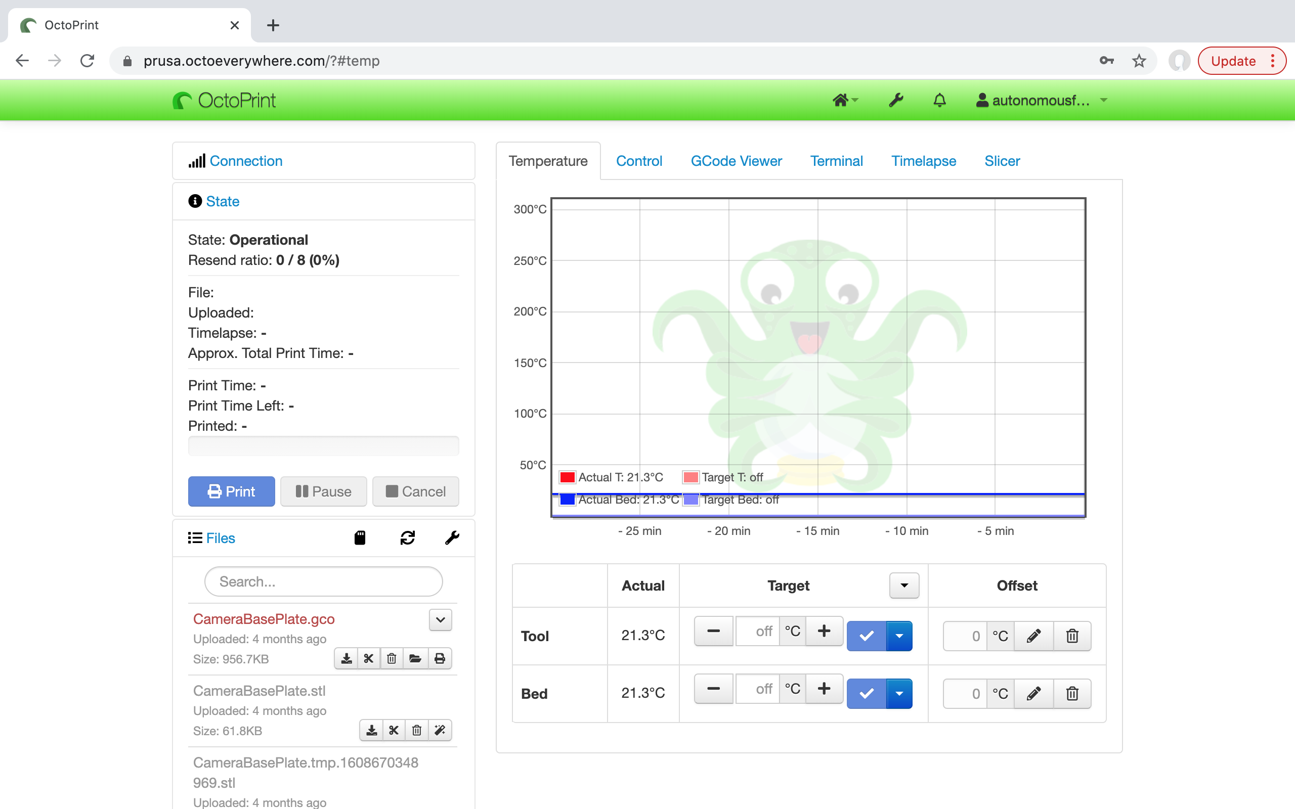
[Figure 25: Octoprint main page]

[Figure 26: CAD Slicer]

[Figure 27: MQTT command for direct user control of robot]
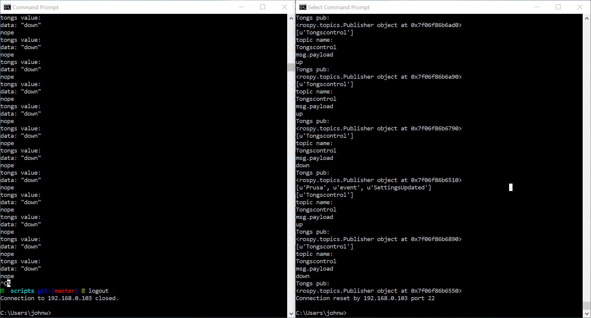
[Figure 28: command prompt on the left is the robot confirming it receives and is reacting to user command. Command prompt on the right is the protocol conversion software at work converting MQTT protocol user command from Octoprint to ROS topic protocol]
Design Analysis and Optimization
Component Sizing Analysis and Optimization
Autodesk Inventor Professional was used to confirm the initial design sizing and setup of components and the simulated factory layout. By developing a CAD rendering of the setup and design the team was able to accurately determine which components were required to be machined. The design was optimized to reduce the need to machine due to the constraints of not having very accurate machinery at the teams disposal due to the ongoing COVID 19 situation. The reduction in machined components would greatly increase the tolerancing of the final design. Therefore, stock component lengths were kept as close to the original raw components. Additionally, the final CAD model helped to assess the center of mass for the winch system to ensure the system to be stable during the lifting and lowering actions. Please refer to Appendix A & B for further details on the CAD renderings and drawings.
Magnetic End Effector Analysis and Optimization
K&J Magnetics Online Thickness Calculator was used to analyze and optimize the electromagnets for use on the end-effector of the robot and the 3D printer build surface thickness. The online software makes use of experimental data to simulate the magnetic force applied onto a steel sheet of variable thickness. This allowed the team to choose appropriate electromagnets and build surface thickness to remove the build surface from the 3D printer. This also helped the team analyze the magnetic force from the 28 permanent Neodymium magnets under the 3D printer build plate onto the build surface.
The following analysis demonstrated the use of the K&J Magnetics Online Thickness Calculator to optimize the magnet and build surface thickness. Please note that the team had access to existing electromagnets and that they were used for the first analysis.
Assumptions:
- A single electromagnet can be simplified to a Grade 42 Neodymium disc magnet with the same form factor (diameter = 7/8”, height = 7/8”) and pull force of 20kg
- The thickness of the steel spring sheet (build surface) is 1 mm (approx. measurement)
- A single magnet on the bottom of the 3D printer build plate is a Grade 45 Neodymium block magnet with a form factor of 20x6x2 mm.
Figure 29 shows the simulation for the electromagnet force on the 1 mm steel sheet and Figure 29 shows the simulation for the build plate magnet force onto the 1 mm steel sheet.
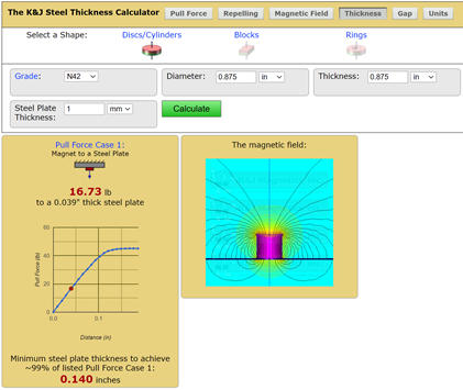
[Figure 29: electromagnet pull force]
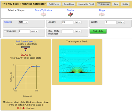
[Figure 30: build plate magnet pull force]
We calculated the combined force from the 4 electromagnets to be 66.92 lbf and the combined force from the 28 build plate magnets to be 103.88 lbf. Therefore, the force from the build plate magnets were greater than the force from the electromagnets. Hence, the build surface could not be lifted with the assumed electromagnet and build plate thickness without further modifications. As such we proceeded with the calculations using Coulomb's Law to justify the addition of a separation aluminum plate with a thickness of ⅛ inches as outlined in the Initial Design Investigation section. With the addition of the aluminum plate the magnets are able to lift the steel sheet off using only 46lbf.
Codes and Standards
The robot is designed to operate in factories and other work environments. To ensure the robot could safely operate in these settings, we made the robot design conform to a rigorous set of codes and standards. The CSA Z432-16 Standard “Safeguarding of the Machinery” strongly suggests the installation of multiple kill switches that can immediately disconnect a machine’s powersource. [6] On our robot, we have installed two devices that can immediately stop the robot: a simple toggle switch and an emergency stop push button. The emergency e-stop has the standard red mushroom shape that is ubiquitous in factory environments.
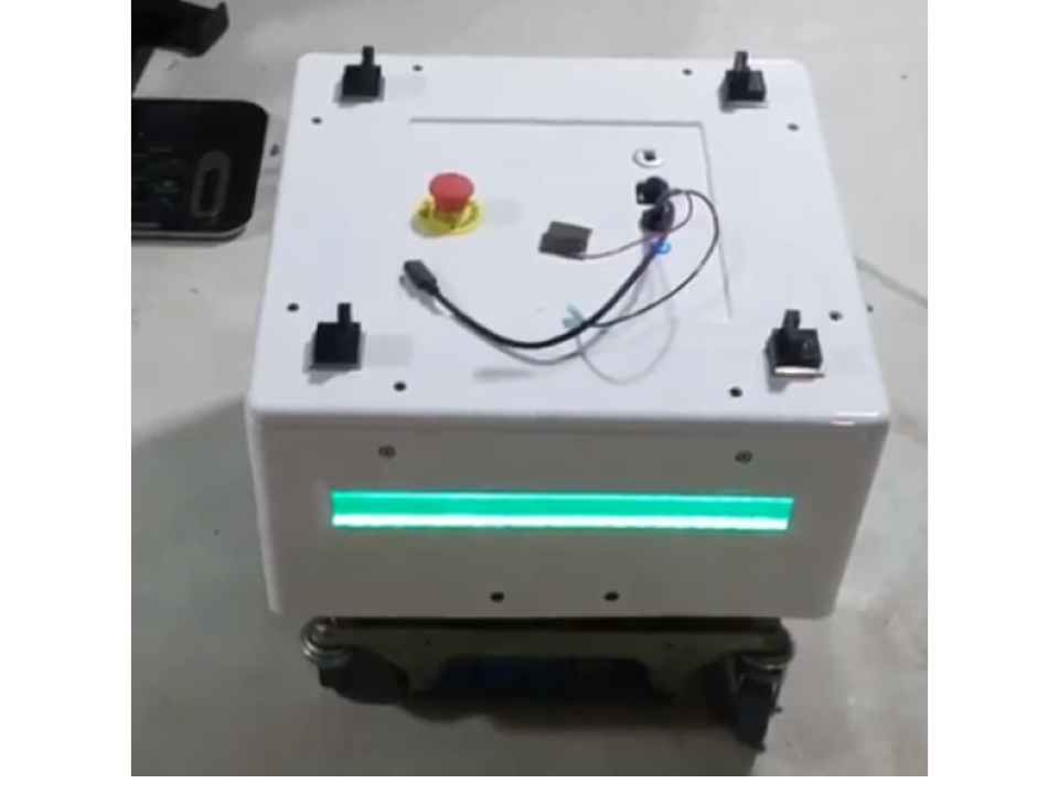
[Figure 31: Limit Switches Mounted on Robot]
Open Source and Licensing
The project is entirely is open source distributed under the MIT Permissive Free Software License. All software used in this project is available at this link: https://github.com/CallMeSwal/Mobile-ROS-Robot-For-Automating-3D-Printers. All CAD files are available on GrabCAD: https://workbench.grabcad.com/workbench/projects/gcWAaForEepOvABII1KwOmdpAaRL4rqbquw3CNFsa1Siry#/space/gc75CU9bmHHaPMr1YX_k_IzmtHOvn8PGeHFgD3TjWPh78q. The project is built on several other open source projects (ROS, OctoPrint, Python, librealsense, AprilTag-ROS). All of these softwares are distributed for free for educational purposes. More details about these lisences can be found on each of these project's respective github pages.
Project Team Members
Parth Patel, John Wang, Swaleh Owais