Close
0%
0%

Mini Cube Robot

A small 5x5cm Cube Robot with differential two wheel drive. Modular design with a simple and cheap base.

Similar projects worth following
This is, as the name suggests, a Mini Cube Robot with dimensions 5x5cm. It is designed to be cheap, simple and easily expandable through additional stacked modules. The base of the robot is formed by a differential drive drive-train that uses two cheap M10 sized brushed motors with a planetary gear and encoders as well as 6 IR reflective and 4 contact sensors, 3 (2) for the front and 3 (2) for the back. All this is controlled by the Motor Drive PCB, which additionally also act as the power supply for the whole robot. Any additional features can easily be added by stacking additional modules/PCBs on top.

Some add-on boards in development:
- A simple LiDAR board using six ToF sensors (VL53L5CX)

Other modules are planned like:
- A main control and communication board (probably using a STM32F4 or STM32H7 with bluetooth and NRF24L01+ radios)
- A dedicated processing board using either a FPGA or a SoC, or a combination of both

Background

The idea behind this robot is to create a cheap, small and simple robot platform that has all the basic features in a fixed basis and to which additional features can easily be added. Making the basis cheap, small and simple allows the robot to be built in large numbers, for use in cooperative and swarm robotics.

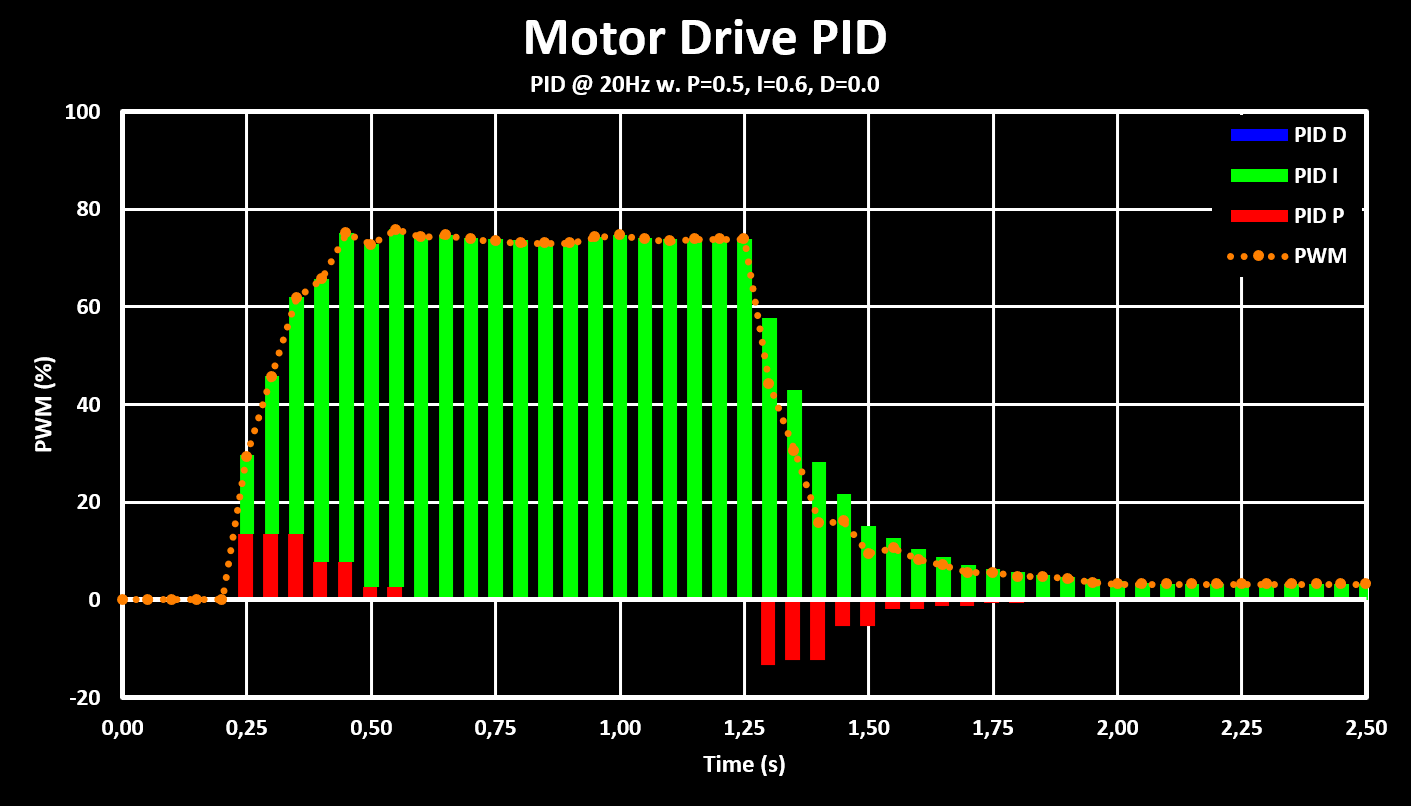
This is planned to be a long term project, over several years, to be expanded upon and adding features both through new hardware and software algorithms. The first phase is to develop the robot base, both the drive mechanics and control software as well as the basic collision sensor acquisition and tuning.

There are a few modules already planned, with some in early design phase:
- A main control and communication board (probably using a STM32F4 or STM32H7 with bluetooth and NRF24L01+ radios)
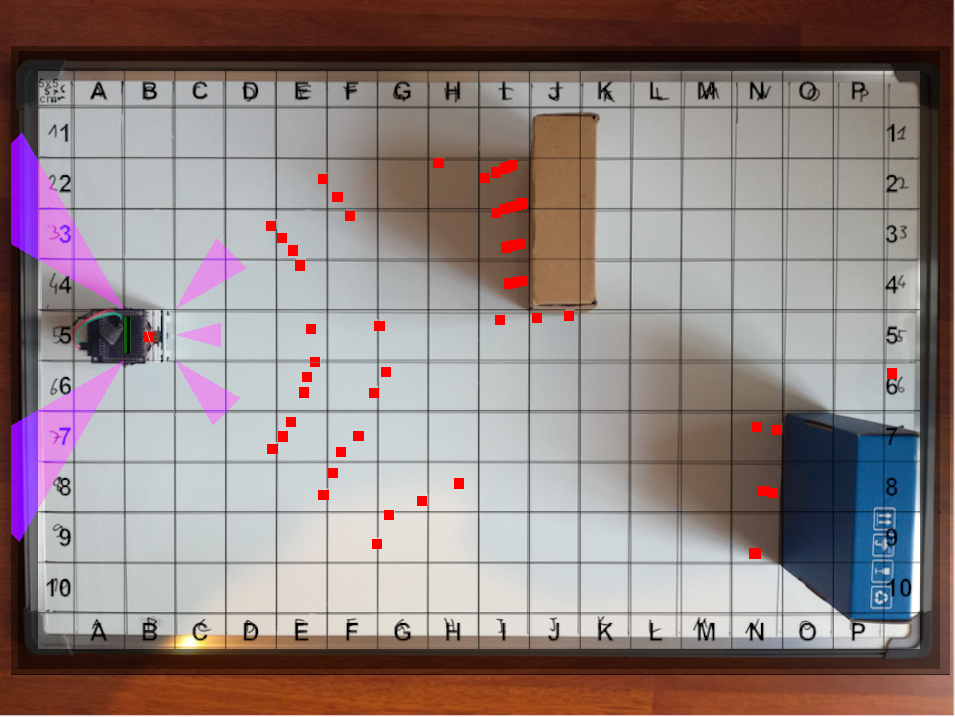
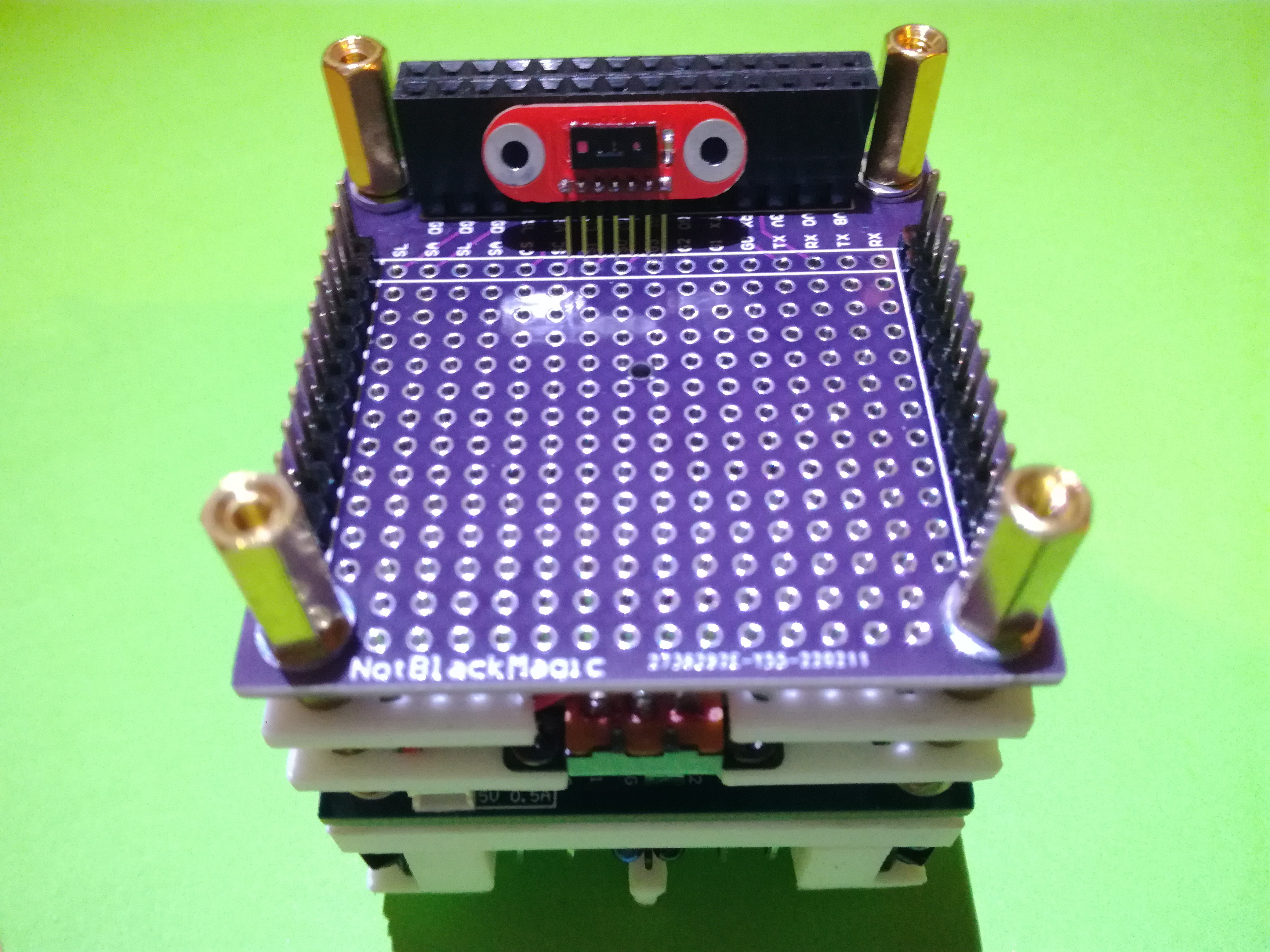
- A sensor board for the top with IMU and a couple of ToF sensors, forming a cheap low resolution LiDAR
- A dedicated processing board using either a FPGA or a SoC, or a combination of both

Besides the hardware there are many software algorithms to be implemented and tested, under others:
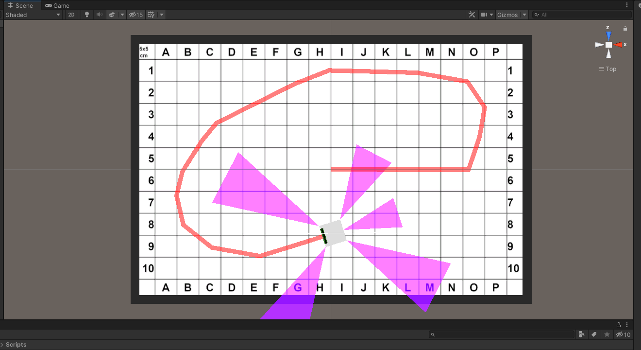
- Integration with PC software, including ROS (python library) and maybe Unity (C# library) with a costume environment
- Localization, and SLAM, with simple sensors, without high resolution LiDAR
- Path planning with different path finding algorithms (A*, RRT, RDT, FM)
- Cooperative and swarm robotics

Hardware

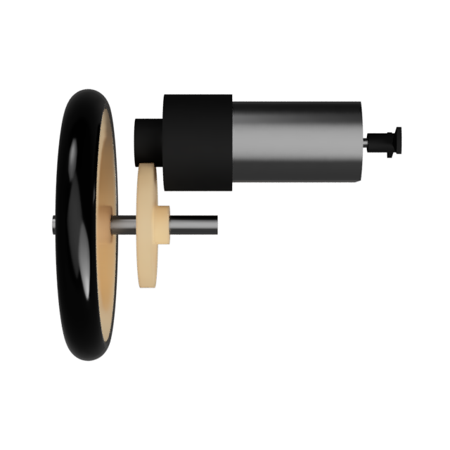
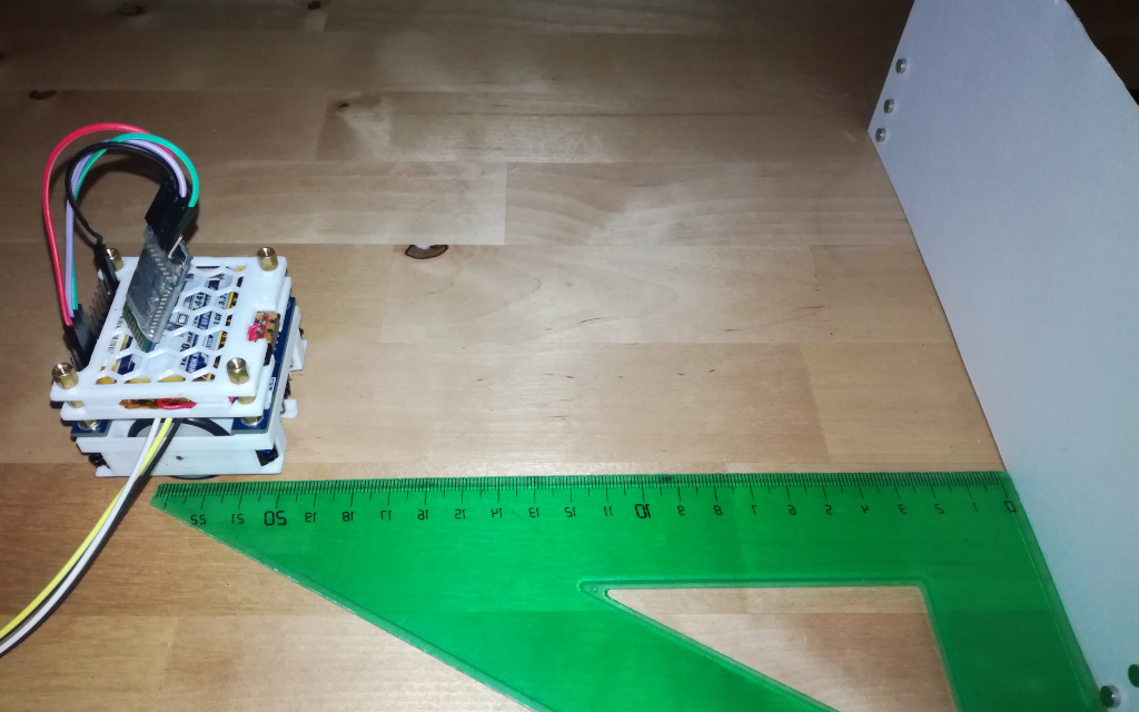
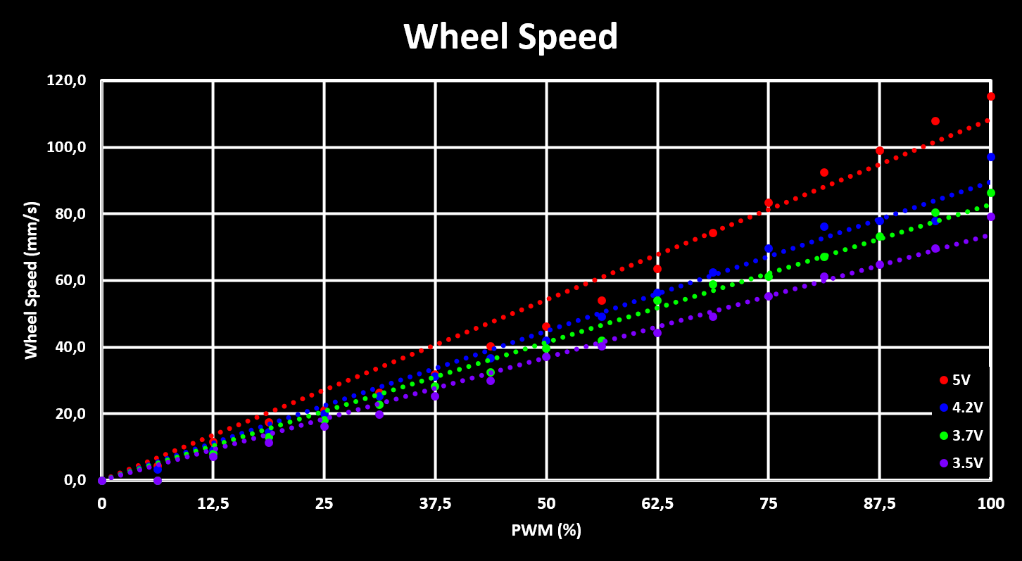
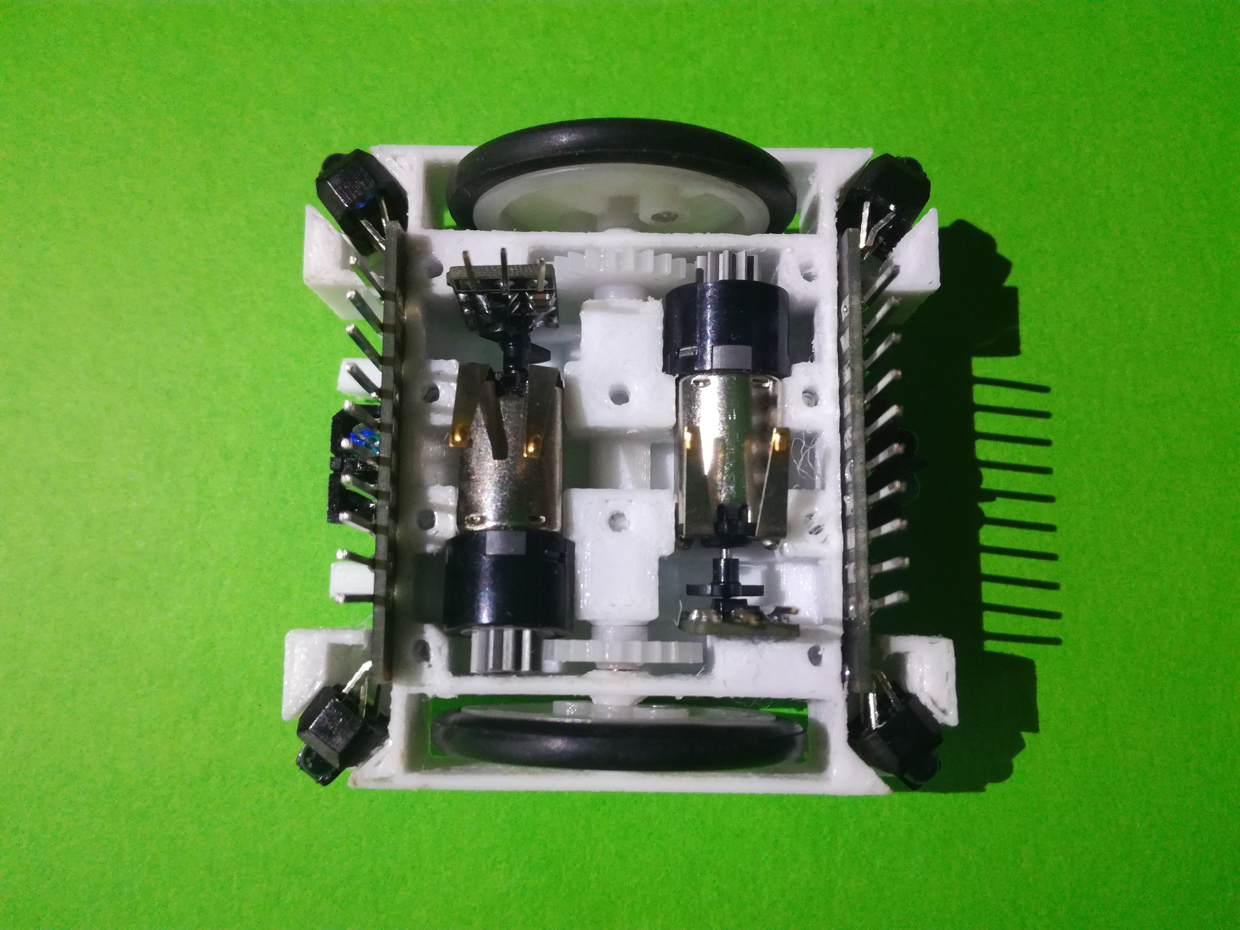
The robot basis is built around the drive-train which is powered by two M10 Brushed Motors with planetary gears and a plastic leaf for the encoder. The output of the planetary gear is a 11 tooth modulus 0.5 gear that drives a 24 tooth gear on a axle that is connected to a wheel. The wheels are made out of a 24mm diameter plastic pulley with a 26x3.1mm outer diameter O-Ring as a tire.

This whole drive assembly is hold in place by two 3D printed parts, the Drive Bottom Holder where all is mounted into and the Drive Top Cover which closes the mechanics off. The Drive Bottom holder also has place for Collision Sensor Boards, in the front and back, as well as a place for two Motor Encoder PCB, one for each motor. On the bottom of the Drive Bottom holder there are mounting places for plastics skids, used to make the robot stable by adding a third, and forth, contact point with the ground.

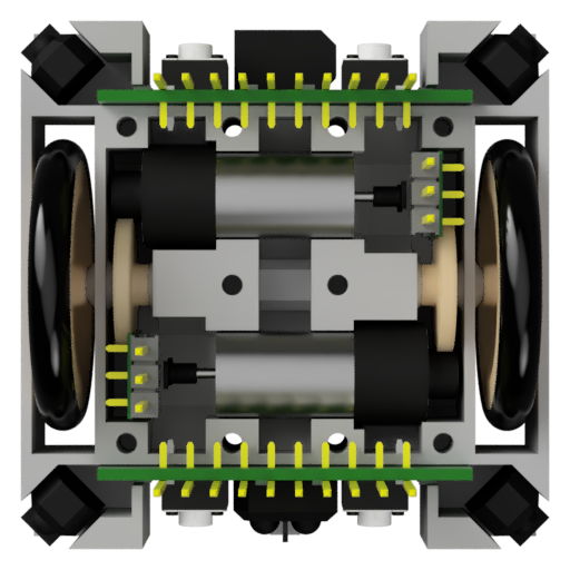
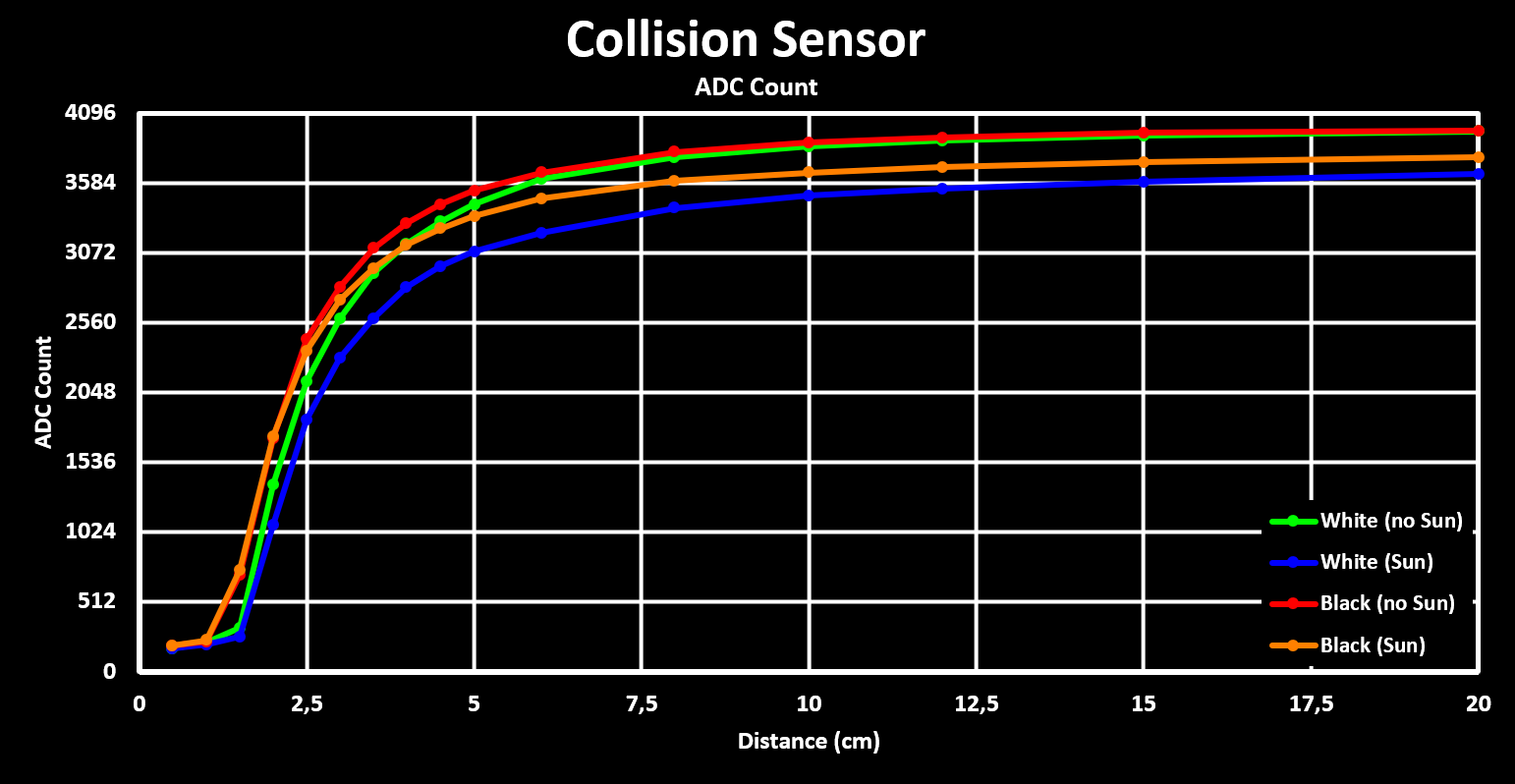
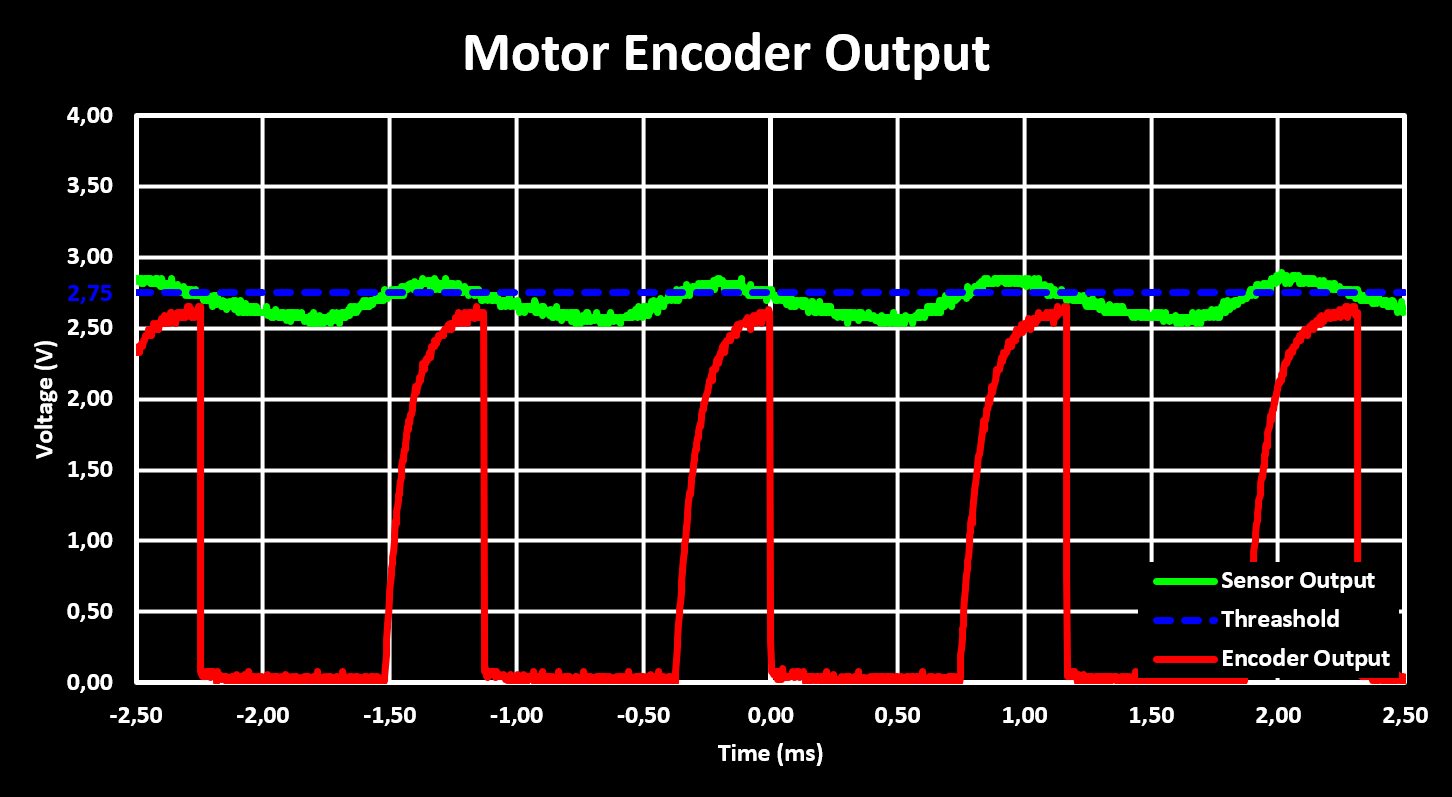
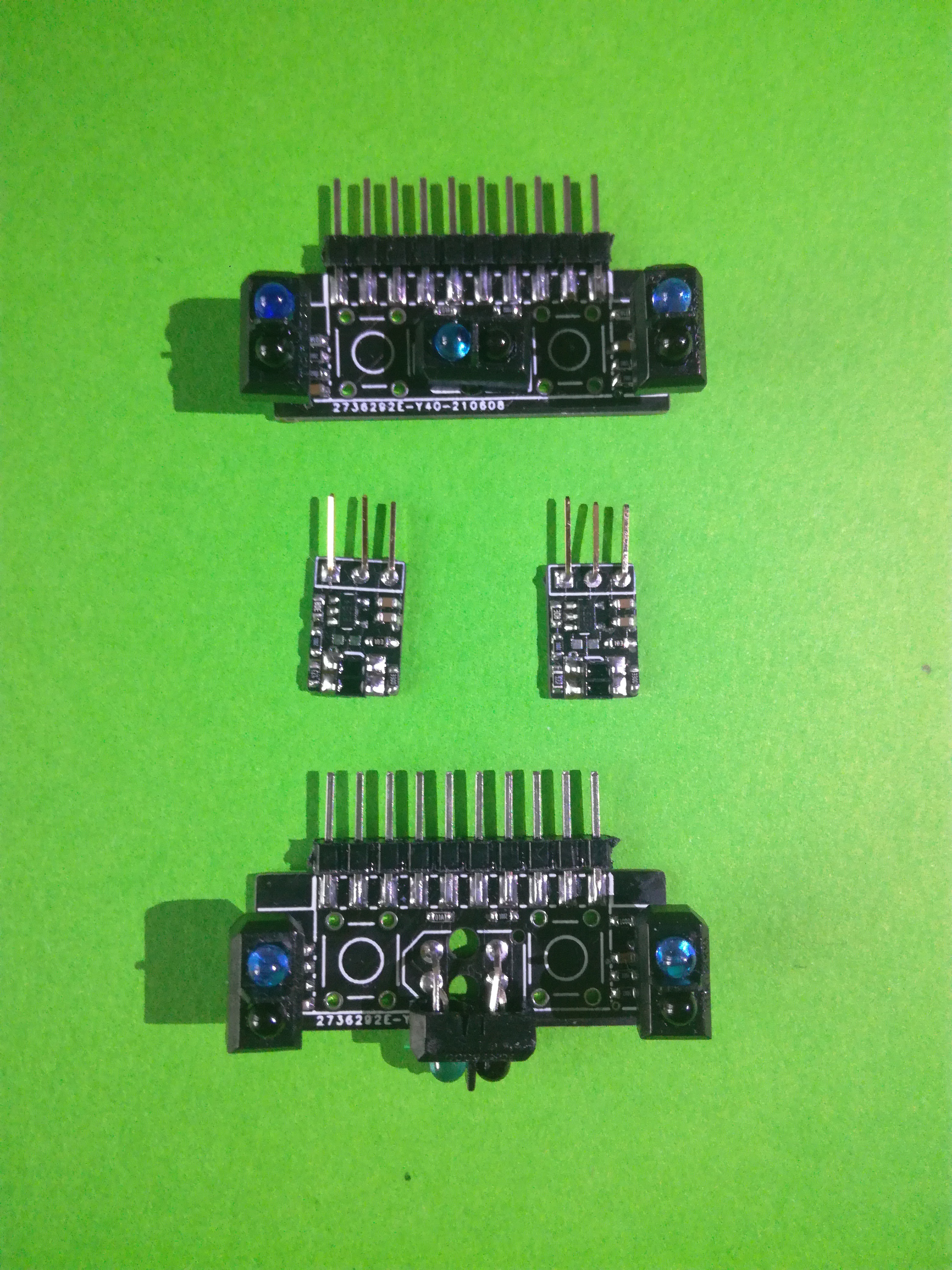
Each Collision Sensor Board holds two contact collision sensors, buttons, and three IR reflective collision sensors (TCRT500). The PCB slides into place and connects to the Motor Drive PCB for acquisition and control. The two Motor Encoder Boards each use a IR reflective collision sensor (ITR8307) together with a voltage comparator to output a pulse each time the motors plastic leaf passes in-front of it.

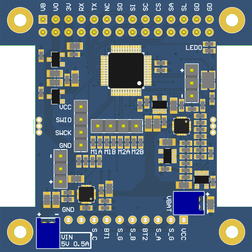
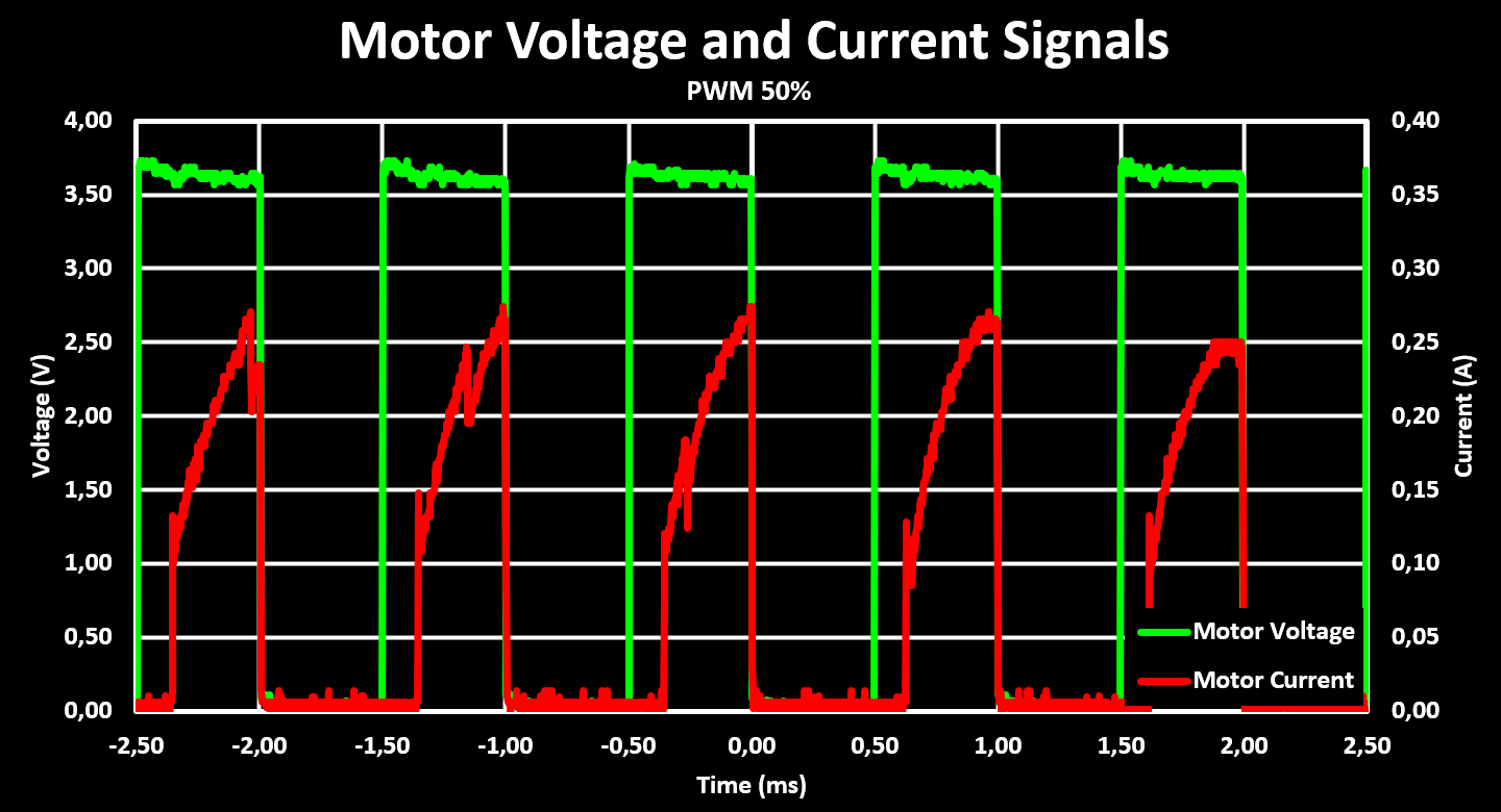
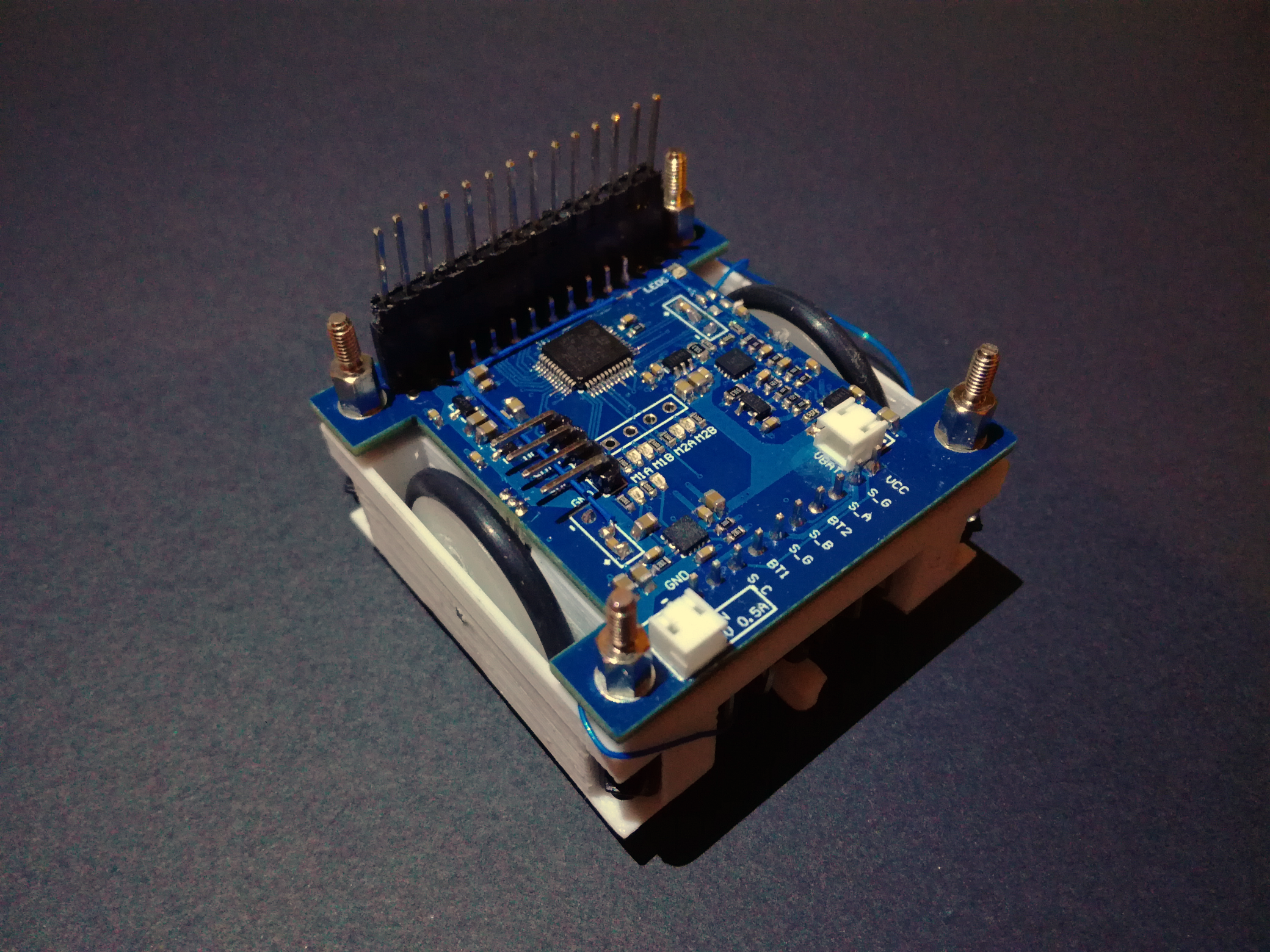
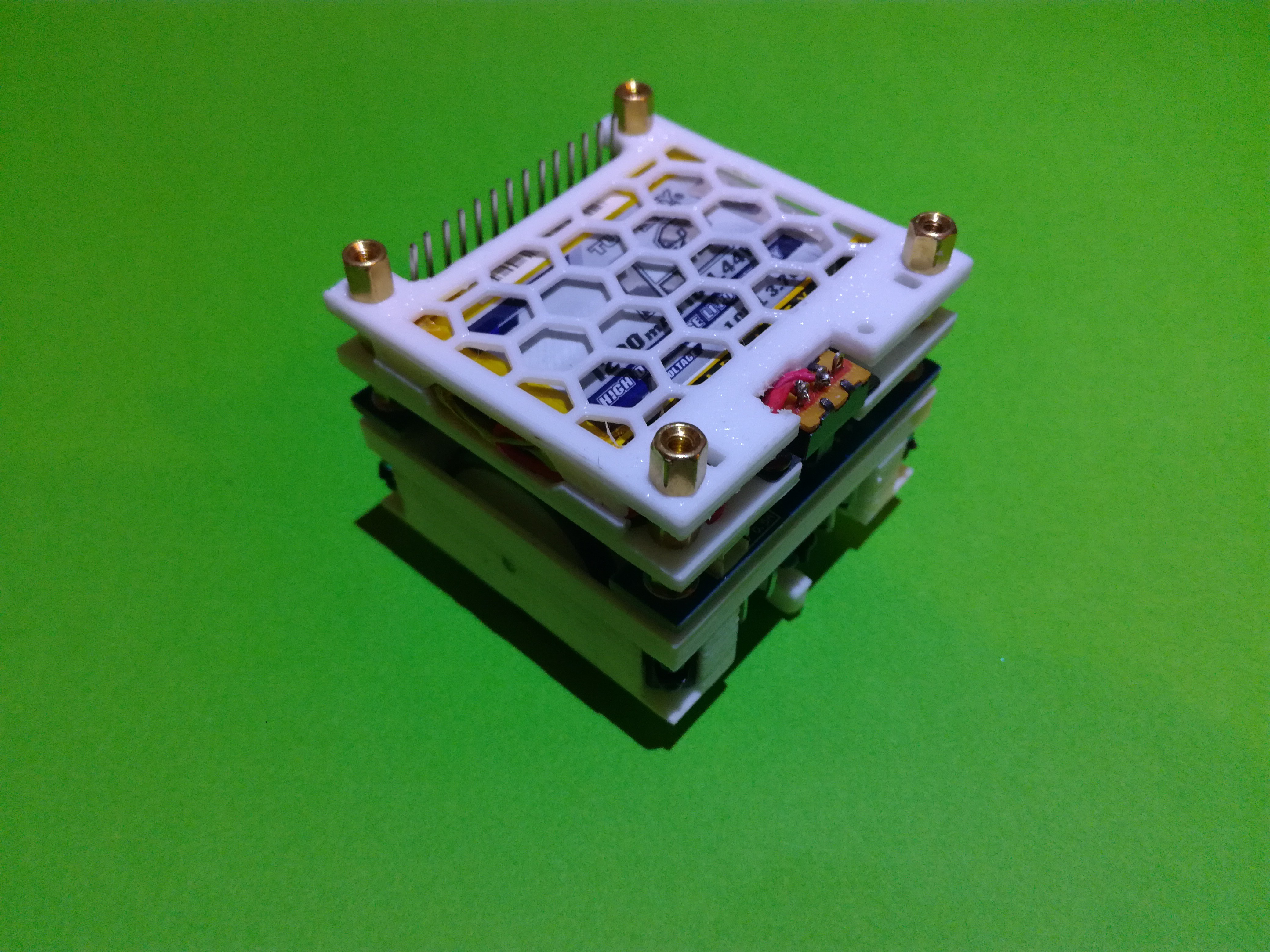
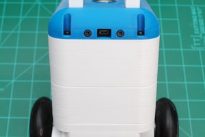
The Motor Drive PCB is the heart and brain of the Mini Cube Robot platform. It has at its core a STM32F103C8 MCU that controls the dual H-Bridge motor driver, STSPIN240, acquires all the sensors and does the interface with the rest of the robot, future modules, over an expansion header with I2C, UART and SPI interfaces. The Motor Drive PCB also is the power supply for the robot through a 1S LiPo that is connected to a battery charger and manager IC, the BQ24230. The Motor Drive Board provides both raw battery voltage rails as well as a dedicated 3V3 rail on the expansion header for other modules.

This project is in very early...

Read more »

Adobe Portable Document Format - 736.56 kB - 09/12/2021 at 14:22

Preview
Download

x-zip-compressed - 47.54 kB - 09/12/2021 at 14:22

Download

Adobe Portable Document Format - 114.03 kB - 09/12/2021 at 14:22

Preview
Download

x-zip-compressed - 6.19 kB - 09/12/2021 at 14:22

Download

Adobe Portable Document Format - 140.41 kB - 09/12/2021 at 14:22

Preview
Download

View all 10 files

  • 1 × STM32F103C8 Microprocessors, Microcontrollers, DSPs / ARM, RISC-Based Microcontrollers
  • 1 × STSPIN240 Low voltage dual brush DC motor driver
  • 6 × TCRT5000 IR reflective sensors
  • 1 × BQ24230 Lithium-Ion Battery Charger And Power-Path Management IC
  • 2 × M10 Motor w. Planetary Gearbox

View all 7 components

  • Add-On Board: LiDAR

    NotBlackMagic05/15/2022 at 17:16 0 comments

    The first add-on board for the Mini Cube Robot is here! It is a LiDAR board based around the VL53L5CX ToF sensor from STMicroelectronics. This ToF sensor has 8x8 separate ranging zones and a 45° by 45° FoV, giving it a angular resolution of 5.625°, with a maximum range of 400 cm in low light conditions. It also has a fully programmable I2C address, allowing the connection of multiple sensors to a single I2C bus.

    A simple breakout board for the VL53L5CX ToF sensors was designed, which holds the necessary decoupling capacitors and pull-up resistors. The module has a 1.25mm pitch header space to which a 7-pin 1.25mm JST connector can be soldered to. Up to six of these modules are hold in place, 45° apart, with a 3D printed holder and connected to the main board.

    The main board uses a STM32F103RCT6 at its core, and it powers, controls, acquires and aggregates up to six VL53L5CX ToF sensors. All sensors share a single I2C bus but have separate power down and interrupt GPIO lines, allowing the programming of unique I2C addresses at start-up. Bellow is a picture of the LiDAR add-on board: the main board with the 3D printed holder and two VL53L5CX sensor modules:

    The set-up above gives a aggregated horizontal FoV of 90° with 16x8 ranging zones. This can be expanded to a FoV of 270° horizontally with 48x8 ranging zones, when all six modules are added. With that configuration, the maximum readout rate is around 5 Hz, due to the limited I2C bandwidth of the used MCU (max. 400 kBits) and each acquisition being quite large at around 1.4 kBytes.

    The aggregated ranging information is then sent over Bluetooth to the Robot Hub software, where it is rendered as a point cloud. An example of this can be seen in the picture bellow, where the Robot Hub rendered point cloud is overlayed with a picture of the real scene:

    The LiDAR add-on board still requires tuning of the ToF sensor settings and acquisition optimizations. Also, it was not yet tested fully populated. At the same time software for mapping and localization will also be developed, in C# for the Robot Hub, starting with ICP. The basic ICP algorithm is already implemented and updates are posted to Twitter.

    The firmware of the LiDAR Main Board is available on GitHub and schematic and gerber files of both the VL53L5CX breakout module and the main board are available on the website, as well as some additional information about it.

  • Odometry and Robot Hub

    NotBlackMagic03/11/2022 at 09:24 0 comments

    After implementing the motor drive controller it was time to implement movement feedback of the robot, calculating its position and rotation based on wheel rotations, this is, the odometry of the robot. Because this is a differential drive robot it is over constrained, it can only move in two axis: forward translation and the yaw rotation. The forward movement speed is simply calculated by the average wheel speeds, in mm/s:

    And the rotation rate, in rad/s, is calculated with the following formula, where Spacing is the distance between the two wheels in mm:

    Now these values are in the robots local reference frame and have to be converted into a global reference frame that is stationary. With the robot moving on the same plane (XY plane) as the global reference frame, the yaw rotation is the same in both and only the forward translation must be converted into its X and Y translation in the global frame:

    Both the yaw rotation speed and X and Y translation speed must be integrated over time to get the actual position and rotation of the robot. These values are then sent to the PC where they are used to update the robots position and to draw its movement path:

    The above image is from the Robot Hub that is also being developed, using the Unity game engine and  is also available on GitHub:

    https://github.com/NotBlackMagic/MiniCubeRobot-Hub

    Also, the newly developed prototype board for the Mini Cube Robot has arrived and it looks and fits very well on the robot:

    Together with the prototype board, a test module for the VL53L5CX LiDAR sensor from STM was also ordered. This small and "cheap" LiDAR sensor can output a 8x8 range matrix with range of up to 400cm. Looks very interesting to use as a simple range finder and/or LiDAR for the Mini Cube Robot! Already working on testing it, with progress being published to Twitter.

    The updated firmware with the odometry is available on GitHub and some more information odometry and the reference frames are as always available on the website.

  • Motor Drive Controller

    NotBlackMagic02/23/2022 at 19:44 0 comments

    The Mini Cube Robot motors are driven by a dual H-Bridge, with the motor speed controlled with a PWM signal and the rotation direction with a GPIO. Each motor also has a encoder for motor speed, wheel speed, feedback. Both of these where tested and characterized in previous updates. Controlling the PWM signals directly with a simple wheel speed to PWM signal conversion function is not ideal and would not results in a very accurate system, large discrepancies between the desired wheel speeds and actual wheel speeds specially with changes in battery voltage or motor load. Because of this a more sophisticated controller with feedback is used, the ubiquitous PID controller.

    The implemented PID controller only uses the proportional, P, and integral, I, terms, with the I term being the most important one as it is necessary to have a none zero output, PWM value, even with a 0 error signal in the input, which is the case in the steady state with a constant speed. The derivative term was not necessary because the robot drive system is relatively slow responding and naturally dampened, so additional dampening was not necessary.

    The inputs of the PID controller are the desired wheel speeds, in mm/s, and the output is the PWM value used to control the H-Bridge. The PID controller is implemented in fixed point for improved performance and compatibility for fpu less MCUs. It is running at a 20 Hz refresh rate while the encoder calculates new values at a lower 10 Hz rate. The gain values arrived at after some tuning are 0.5, 16384 in Q15, for the proportional term and 0.6, 19661 in Q15, for the integral term. The step response of the controller, for a input step (wheel speed) from 0 mm/s to 70 mm/s and then back to 0 mm/s, is shown in the figure bellow.

    These settings are then used for a simple drive test, shown in the clip bellow, where the robot is controlled over bluetooth, from the PC. The translation speed used is 70 mm/s and the rotation speed use is 45 deg/s.

    This tests shows the robot moving and rotating with the set speeds. It also highlights some problems with the drive train, first it is very loud, some lubrication will be added to help with that as well as testing if increasing the PWM frequency (currently set to 1 kHz) is possible and which should decrease the whining noise. The robot also has some sideways drift, in part because one wheel has a dent in it (from using the hot air gun to close to it…).

    The firmware is available on GitHub and some more information on the PID controller and on the results are as always available on the website.

    New add-on boards for the robot are arriving soon like a simple prototype board for testing some IMU sensors! Stay tuned for early previews of what is to come, for both this and other projects, on Twitter.

  • Reflective Collision Sensor Test

    NotBlackMagic11/25/2021 at 21:16 0 comments

    The robot drivetrain holds two collision sensor boards where each of them has three IR reflective sensors (TCRT5000). This sensor is composed of a IR LED and a phototransistor to sense the reflected IR light from an obstacle. The IR LED is driven through a 100 Ohm resistor, which gives a drive current of around 20mA, and the phototransistor is connected to a pull-up resistor of 10 kOhm that converts its current output to a voltage that is then converted by the MCUs ADC.

    To test the effective range of the IR reflective sensors, the distance that they can sense an obstacle, the setup shown in the figure bellow is used. The robot is set at a known distance from the target and the ADC value of the front facing sensor is registered.

    The test was performed with distances from 1 cm to 20 cm and with both a white and black paper target. All the tests were performed without any sunlight (window shades closed) and with very little indirect sunlight (window shades open but north facing window). This because sunlight has a very high IR content and any high indirect sunlight saturates the phototransistor and therefore obstacles can't be detected at any useful distance.

    Bellow is a figure showing the results for these tests.

    These results show that the IR reflective sensors can be used for distances bellow  around 5 cm, in this range the distance can be, more or less, estimated and without having to worry to much about the obstacle color. This is sufficient for the intended use, to detect an obstacle at a distance (> 1.5 cm) that allows the robot to turn around without having to reverse.

    As always there is some more information and results available on the Website. Also, more frequent progress updates on projects are published on Twitter.

  • Motor Encoder and Drive Results

    NotBlackMagic11/05/2021 at 10:26 0 comments

    Motor Encoder Tuning

    As mentioned in the previous project log, the motor encoders was tuned before gluing them in place. The first part of the tuning consists on setting the reflective sensors LED drive current, by changing the LED drive resistor, and the phototransistor output resistor, which sets the sensibility. The values used are 330 Ohm for the LED drive resistor, a drive current of 6mA, and 47 kOhm for the phototransistor resistor. These give a good output swing when the leaf passes in-front of the sensor, around 250mV, while keeping the current consumption relatively low.

    Next the voltage comparator threshold voltage is set to about the middle of the reflective sensor output swing, which is 2.75V. All these signals are shown in the figure bellow, in green the output of the reflective sensor, in blue the threshold voltage and in red the output of the comparator. The latter one had to be filtered by adding a 10nF capacitor to the output to remove false triggers/pulses caused by noise in the reflective sensor output. This is why it has a slow rise time and a high voltage level bellow 3.3V.

    The tuned motor encoder was then glued in place, the figure above is from the final assembly already, in more then one robot chassis and it always gave a reliable output confirming that with the used resistor values the motor encoder is reliable.

    Motor Drive Characterization

    With the motor encoders working, glued in place and the Motor Drive PCB added on top and soldered on it was time to test the motor drive. The motors are driven with two H-Bridges in a single IC, the STSPIN240. The motor RPM is controlled by using PWM signals to drive the H-Bridge. Bellow is a figure showing the voltage and current at one of the motors terminals. The current is obtained from the INA180 connected to the current sense resistor on the motor output of the STSPIN240.

    The figure shows that there is a slight voltage drop when the current increases, this can maybe be mitigated with higher capacitor values to bridge the current draw spikes but the drop is not large and so not considered a concern.

    Finally, with both the motor drive and encoders working it is possible to characterize the motor RPM vs PWM duty cycle. With that and using the gear ratio and wheel diameter, the expected robot drive speed with different PWM duty cycles values and supply voltages, battery voltage levels, is obtained. This is shown in the figure bellow.

    This figure shows that the maximum expected drive speed of the robot is around 90 mm/s with a full battery (4.2V) and decreases to around 75mm/s when the battery gets empty (3.5V). This means that the robot firmware will have a software limited maximum drive speed of 70mm/s so that the limited maximum drive speed can always reached, with any battery voltage.

    The next step is to characterize the reflective collision sensors.

    A more detailed description of the tuning of the motor encoder as well as some additional results of the motor drive are available on the Website.

    Updates and progress on this project, and other projects, are published on Twitter.

  • Hardware (PCBs)

    NotBlackMagic10/17/2021 at 19:08 0 comments

    This update is focused on the Hardware of the Mini Cube Robot drive-train (base). All necessary mechanical parts have arrived, screws, gears, motors, wheels etc... As well as all three PCBs (Motor Encoder, Collision Sensor and Motor Drive) and the needed components to populate them.

    First all PCBs were assembled and tested for functionality. Both the Motor Encoder and Collision Sensor Boards (in the figure bellow) are working, all sensors are returning a good signal and are working as expected.

    The Motor Drive PCB was also tested, the MCU is working as well as the Motor Drive and Battery Manager ICs. The peripherals are still being tested as well as the acquisition of all the sensors and the control of the motors.

    With the PCBs functionality tested, the first Mini Cube Robot base was assembled. The mechanical parts are fitted into the bottom drivetrain holder, together with the collision sensor boards and the motor encoder boards. The latter have to be glued in place but before that they were tuned so that the voltage comparator returns a clean signal whenever the motor's plastic leave passes in-front of it (results in a future update/log). Bellow is a view of the bottom drivetrain holder fully assembled.

    As can be seen all the parts fit very snug into there locations. The gears make good contact and the motors can spin the wheels perfectly. This is of course not the first version 3D printed, there where quite a few versions before arriving on these. The latest, the ones used here, 3D printed part files are linked to download.

    With this, the top cover was added and the Motor Drive PCB was mounted on top. The collision sensor and motor encoder boards have to be soldered to the Motor Drive PCB, this is something that is planned to be changed in a future version. The assembly can be seen in the figure bellow.

    Looking at the photo there are a few blue wires visible, those connect to the motor encoder IR reflective sensor outputs to monitor if the voltage output changed with the complete assembly. Nothing major was detected and the motor encoder output continued to work as expected.

    Finally the battery pack was added. It is composed of two 3D printed parts, the same part is used as the base and the top just flipped, holding a 1200mA Turnigy (HobbyKing) 1S LiPo in-between them, as well as a power switch. The fully assembled Mini Cube Robot base can be seen in the figure bellow.

    This is the current state of the Mini Cube Robot project. Next is the development of the software for it, to control the motors and read all the sensors.

    For some more details on each part and a first assembly guide are available on the website. The assembly instructions will be added to this project page later.

    Also, updates and progress on this project, and other projects, are published on twitter.

View all 6 project logs

Enjoy this project?

Share

Discussions

teraz wrote 05/21/2022 at 21:03 point

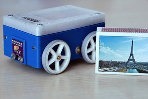
meybe add accelometer to check wall, different bottom etc.

very nice project

  Are you sure? yes | no

NotBlackMagic wrote 05/22/2022 at 15:33 point

I have planned to add a IMU (Accelerometer + Gryo + Magnetometer) but have not thought of using the acceleromter to detect walls (collisions) and the surface types! Its a great idea!

  Are you sure? yes | no

Similar Projects

Does this project spark your interest?

Become a member to follow this project and never miss any updates