 NotBlackMagic
The Mini Cube Robot motors are driven by a dual H-Bridge, with the motor speed controlled with a PWM signal and the rotation direction with a GPIO. Each motor also has a encoder for motor speed, wheel speed, feedback. Both of these where tested and characterized in previous updates. Controlling the PWM signals directly with a simple wheel speed to PWM signal conversion function is not ideal and would not results in a very accurate system, large discrepancies between the desired wheel speeds and actual wheel speeds specially with changes in battery voltage or motor load. Because of this a more sophisticated controller with feedback is used, the ubiquitous PID controller.
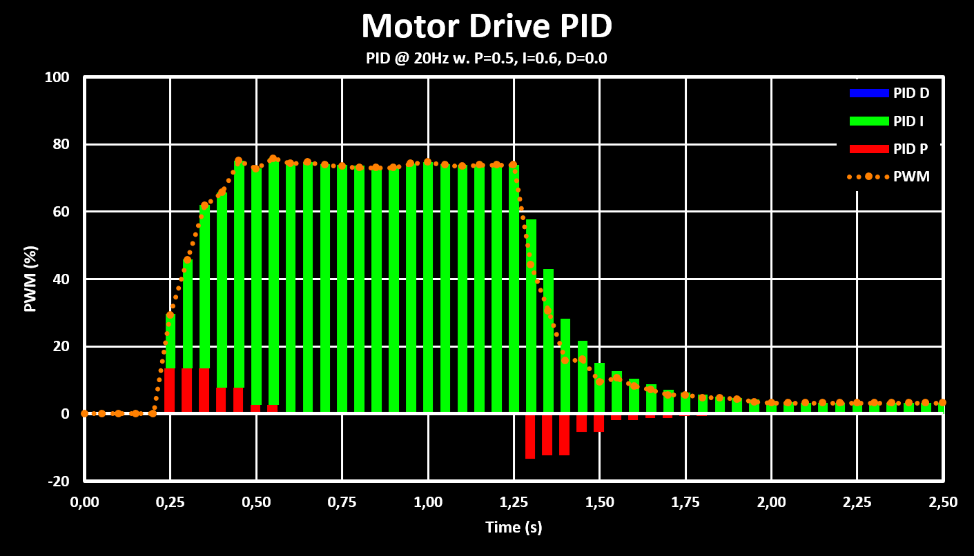
The implemented PID controller only uses the proportional, P, and integral, I, terms, with the I term being the most important one as it is necessary to have a none zero output, PWM value, even with a 0 error signal in the input, which is the case in the steady state with a constant speed. The derivative term was not necessary because the robot drive system is relatively slow responding and naturally dampened, so additional dampening was not necessary.
The inputs of the PID controller are the desired wheel speeds, in mm/s, and the output is the PWM value used to control the H-Bridge. The PID controller is implemented in fixed point for improved performance and compatibility for fpu less MCUs. It is running at a 20 Hz refresh rate while the encoder calculates new values at a lower 10 Hz rate. The gain values arrived at after some tuning are 0.5, 16384 in Q15, for the proportional term and 0.6, 19661 in Q15, for the integral term. The step response of the controller, for a input step (wheel speed) from 0 mm/s to 70 mm/s and then back to 0 mm/s, is shown in the figure bellow.
These settings are then used for a simple drive test, shown in the clip bellow, where the robot is controlled over bluetooth, from the PC. The translation speed used is 70 mm/s and the rotation speed use is 45 deg/s.
This tests shows the robot moving and rotating with the set speeds. It also highlights some problems with the drive train, first it is very loud, some lubrication will be added to help with that as well as testing if increasing the PWM frequency (currently set to 1 kHz) is possible and which should decrease the whining noise. The robot also has some sideways drift, in part because one wheel has a dent in it (from using the hot air gun to close to it…).
The firmware is available on GitHub and some more information on the PID controller and on the results are as always available on the website.
New add-on boards for the robot are arriving soon like a simple prototype board for testing some IMU sensors! Stay tuned for early previews of what is to come, for both this and other projects, on Twitter.
Discussions
Become a Hackaday.io Member
Create an account to leave a comment. Already have an account? Log In.