 zpekic
Refer to the UART basics, and the component source.
UART "receivers" that convert serial bit stream into parallel word and "done" signal are usually implemented as state machines. The trick is to observe the space ('0') state of the RXD input to decide if it is long enough to qualify for start bit, and determine the mid-point of the start bit to sample data bits at 1 / baudrate time intervals after that. Once the whole frame is counted, the state machine needs to be reset to initial state and watch for start bit again. There is some complexity to such state machine, which has to run over twice the frequency of the incoming data stream (sampling theorem), but in reality much faster, usually 4 or 8 times faster.
It can be simplified, and no state machine is needed, with a simple observation:
- if we have n / 2 + 1 mark bits ('1') in row (e.g. 3 for baudrate * 4), then it must be either a data 1, or a stop bit
- if at the same time, there are n / 2 + 1 space bits frame time in the past, then this must be a stop bit, and everything between is a data frame
With this, one has to simply have a 44 bit shift register (max 11 bits per frame supported * clocked at baudrate * 4), which receives RXD on the right (shift up), and simultaneously acts as a delay line. The stop bit is detected at the right side ("now"), and start bit at the left side ("past").
The operation mode is given by 3 mode bits:
| mode | data length | parity | frame length |
| 0XX | 8 | none | 10 |
| 100 | 8 | space (0) | 11 |
| 101 | 8 | mark (1) | 11 |
| 110 | 8 | even | 11 |
| 111 | 8 | odd | 11 |
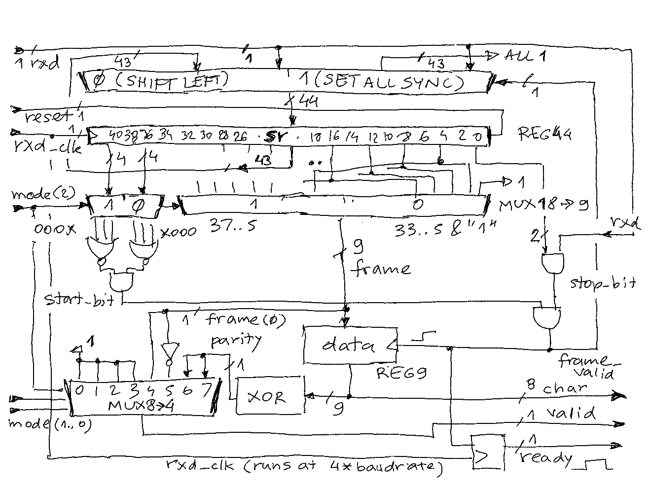
The schematic below attempts to describe the circuit, which could also be constructed with less than 20 off-the-shelf 74XX logic IC.
- 44-bit shift register "sr" is driven by rxd_clk which is 4*baudrate. It has both async reset (at restart to set it all to "1", which will prevent error start bit detection (remember, start bit is "0"), and sync reset which must happen when a frame_valid signal is detected. Otherwise, it just shifts up the rxd input one place left ("shift up"). This means the more MSB the bit is, the more in the past it is. This is implemented with a register and dual input MUX. Note that at "sync reset", the LSB will be the rxd input to prevent loss of input stream during this moment.
- Given that this receiver supports 10 (no parity bit) and 11 bit UART frames (parity present), the start bit can be either at 43..40 or 39..36. That is the task of the upper MUX driven by mode(2). The lower MUX samples 9 bits out of the remaining 40 from sr, 4 bits apart, and close to mid-point of the bit time. When the mode(2) = 0 (10 bit frame), the LSB is forced to "1", otherwise it is picked up from sr register and represents the parity bit which is right before stop bit.
- The start bit detection works on the upper 4 bits of frame. To detect a "0", 3 contiguous bits out of 4 must be 0, therefore the NOR/AND generates "1" when start is 000X or X000.
- The stop bit detection works at the end of frame - 3 contiguous bits must be 1 - this includes 2 at the end of sr and the current rxd. This is a "look-ahead" that saves one clock time delay in the circuit.
- If the start_bit is 1 and stop_bit is 1, we have a frame_valid. This signal is used to capture the 9-bit (data + 1 bit parity) into the "data" register (so that the shift register sr can continue to run and capture the serial stream)
- 9-bits from the data register are fed to standard parity-generating XOR ladder. The upper 8 bits are presented to output as "char" parallel data, but with bits flipped (because of the order how bits are sent in UART protocol)
- 3 mode control input bits select the valid output signal, with modes 0XX always generating "1" because frame has no parity, while modes 1XX take the parity into consideration (NOTE: valid signal is not used nor was it tested in this design, may have bugs!)
- ready signal is frame_valid delayed 1 clock to ensure data register by that time already contains the stable data from the frame MUX. The ready will we 1 clock time wide pulse, and at can be used as latch, rising edge, or falling edge trigger to indicate to parallel receiver that char output has valid 8-bits from the UART frame.
Discussions
Become a Hackaday.io Member
Create an account to leave a comment. Already have an account? Log In.