 Michael Gardi
I've been in a bit of a holding pattern waiting for external stuff to happen. For instance my local makerspace is in the process of rewiring the woodworking shop which includes the CNC that I want to use to mill the walnut side panels. In the mean time I have been taking the pre-requisite online courses in order to qualify on that particular piece of equipment.
Similarly I have been waiting for Dave's keyboard kit to arrive (from osiweb.org - a complete replacement keyboard for the Sol-20). According to the USPS tracking it is currently in Toronto which is about 100km from where I live, hopefully this will arrive tomorrow.
Even though I can't make the walnut side panels right away I decided to get going on the Sol-20 case. In addition to creating the reproduction keyboard, Dave has also produced DXF files for the side panels.
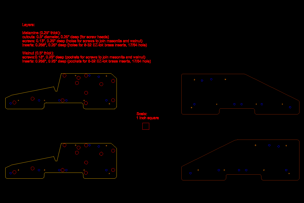
As you can see there are two distinct parts. There is the outside panel that will be milled from walnut, and an inside panel onto which the blue console pieces will rest. There are a lot of cutouts on the inside panel that were used to attach internal components from the original design like the 5-slot S-100 bus cage and power supply. In my much simpler reproduction these will not be used.
With the side panels pretty much a known quantity, there were still many unanswered questions. For instance how wide are the blue console pieces? I know the size of the keyboard cutout from Dave's KiCad files, but how is it positioned relative to the edges of the case?
Well redjr16 to the rescue. Rick, who actually owns a Sol-20 (I'm totally jealous), was kind enough to take the time to answer these questions, take pictures, and more. Thanks Rick!

With these measurements I was confident that I could produce a Sol-20 body that was pretty close to the original's. I loaded the DXF files into Fusion 360 and produced STL files for each of the side pieces. Then I brought these STL files into TinkerCAD so I could noodle around with the design. Here is what I ended up with.
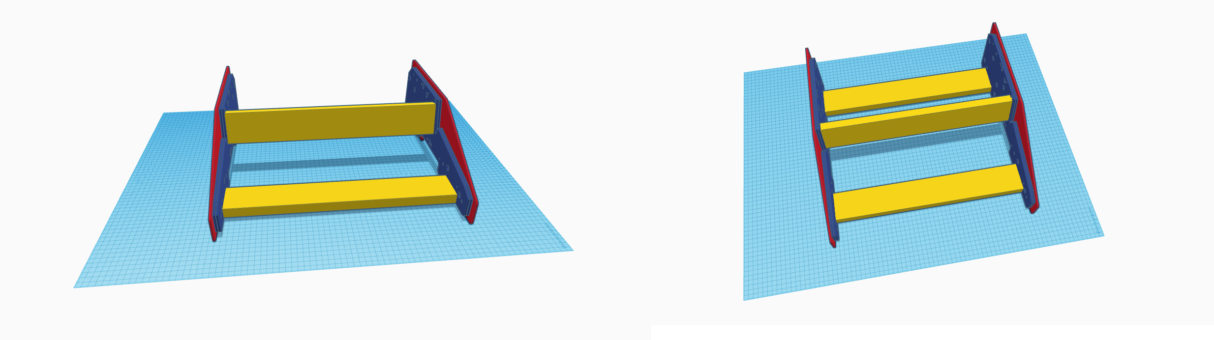
I used the laser cutter at my makerspace to cut four of the inside panels (blue) and two of the outside panels (red) from 3 mm hardboard. The outside pieces will be used as templates when producing the final walnut panels, but in the mean time I can use them as stand-ins while I work on the case panels. The cross pieces (yellow) are 1" x 3" pine cut to 434 mm lengths and are attached to the inside pieces with #8 x 1 1/4" flat head wood screws (in which the heads should end up being flush with the panel). Outside pieces are for the moment bolted to the inside with M3 x 12mm bolts and nuts using existing holes.

Using the inside panel DXF outlines as a guide, and with additional pictures from Rick, I modelled the keyboard panel seen in the rightmost photo above. I lucked out because the width of the panels (446 mm) will just fit on my printer if split in two. The pieces are then glued together and reinforced with cross beams.
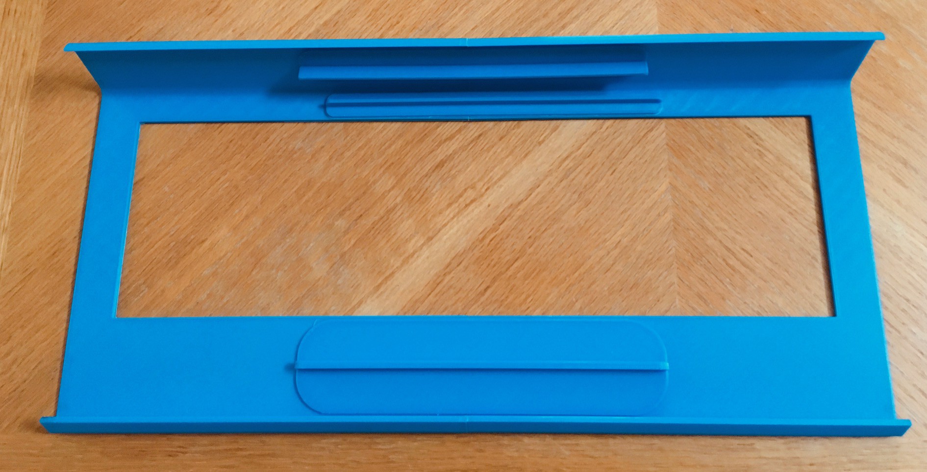
The panel is 3 mm thick which seems to be sufficient to prevent sagging in the middle. It shouldn't be too hard now to finish the rest of the console pieces.
Discussions
Become a Hackaday.io Member
Create an account to leave a comment. Already have an account? Log In.
Thanks Rick.
Are you sure? yes | no
Great progress Mike! That really looks nice.
Rick
Are you sure? yes | no