 Michael Gardi
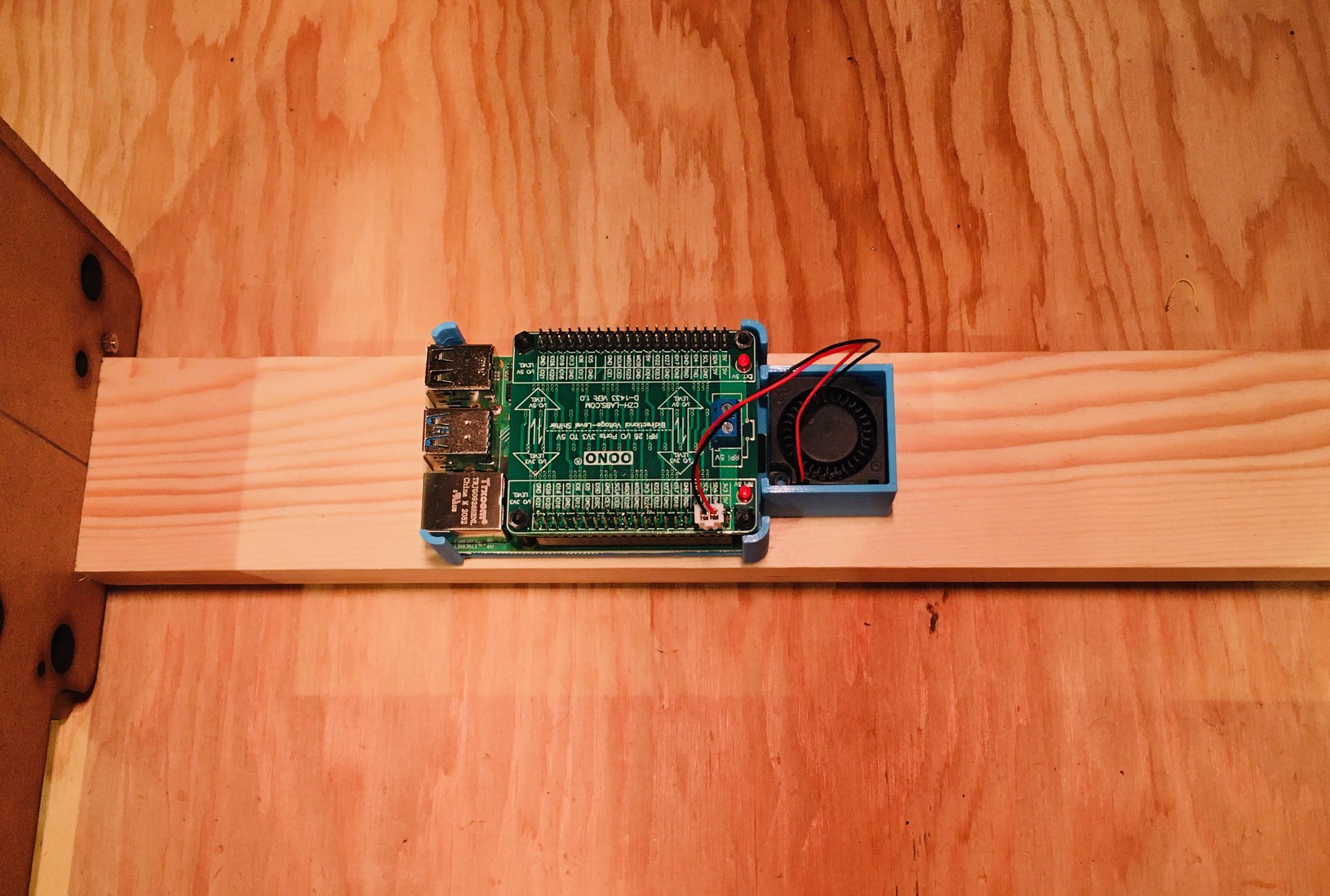
The keyboard encoder is expecting 5V while the Raspberry Pi 4 operates at 3.3V. So to overcome this I purchase a Voltage-Level Shifter Module from Amazon. I also printed a "caddy" to hold the Pi 4 in place and added a small 30 mm x 30 mm x 10 mm blower fan for good measure to keep things cool. The fan I used is from Amazon: GDSTIME 3cm 30mm x 10mm 5V DC Brushless Small Blower Cooling Fan, with Dual Ball Bearings. The fan and the keyboard will be run off of the Pi's power supply. The Pi is secured in place to the caddy with two sided tape.

I then mounted this unit onto the back support of the Sol-20 frame again using two sided tape. The USB and HDMI ports are facing to the rear of the unit.
So we are ready to wire the keyboard to the Pi. Here is what the Sol-20 header pinout looks like.
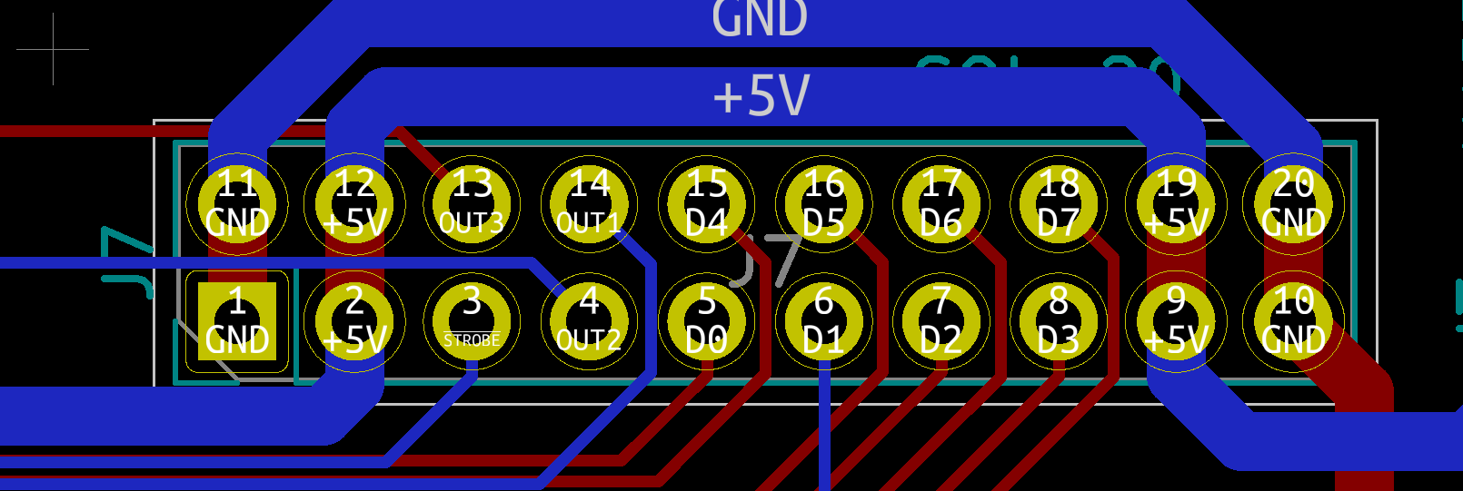
And the Raspberry Pi level shifter hat.

So here is how I wired the keyboard. Note that for the exception of +5V and GND lines which are wired to the 3.3V side or the level shifter, all of the other connections are wired to the 5V side.
| Keyboard Encoder | Raspberry Pi | Description |
|---|---|---|
| 5V | 5V | Power |
| GND | GND | |
| D0 | GPIO6 | Key 0 bit (low) |
| D1 | GPIO13 | Key 1 bit |
| D2 | GPIO19 | Key 2 bit |
| D3 | GPIO26 | Key 3 bit |
| D4 | GPIO21 | Key 4 bit |
| D5 | GPIO20 | Key 5 bit |
| D6 | GPIO16 | Key 6 bit |
| D7 | GPIO12 | Key 7 bit (high) |
| STROBE | GPIO5 | Key ready on falling edge. |
| OUT1 | GPIO23 | LOCAL button. Toggle. HI when LED on. |
| OUT2 | GPIO22 | BREAK button pressed when rising edge. |
| OUT3 | GPIO24 | RESET button pressed when falling edge. |
Here is what the wiring looks like.

I'm investigating a BREAK key issue with Dave, but otherwise everything is working great. The keyboard is now integrated with the emulator. Getting close. Very exciting.
Discussions
Become a Hackaday.io Member
Create an account to leave a comment. Already have an account? Log In.