 Michael Gardi
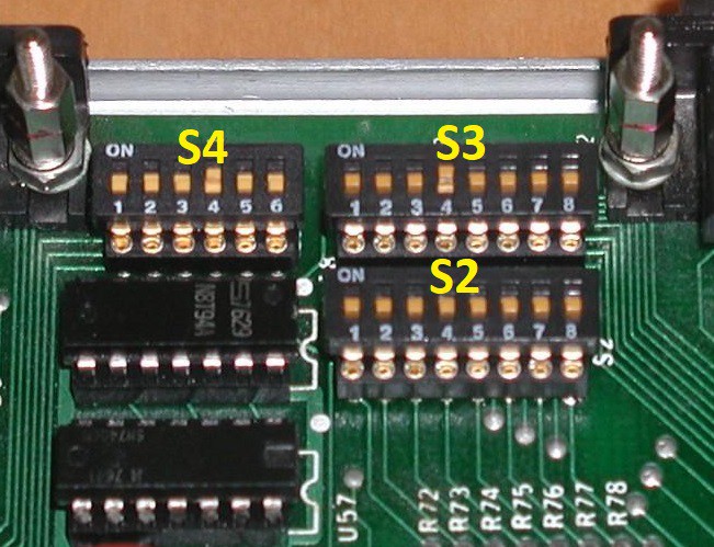
The Sol-20 had 4 banks of DIP switches on the motherboard to control various aspects of the machine's operation. Here's a photo of three of them.
I didn't see an advantage to using physical switches for my emulated hardware so I created a configuration file instead.
# SOL-20 SWITCH FUNCTION DEFINITIONS
#
# This configuration file replaces the four physical setup switch banks on the Sol-20.
#
# Display Control
#
S1-1 = 0   # 0-Run  1-Restart to Zero.  (N/A for emulator.)
S1-2 = 0   # Not used.
S1-3 = 0   # 0-Show control characters. 1-Blank control characters (ASCII values < 32).
S1-4 = 0   # 0-Colored characters on black background. 1-Black characters on colored background.
S1-5 = 0   # 0-Solid or NO cursor. 1-Blinking cursor. (NOTE: Requires apscheduler - "pip install APScheduler")
S1-6 = 1   # 0-Blinking or NO cursor. 1-Solid cursor.
S1-7 = 0   # 0-White screen. 1-Green screen. 2-Amber screen. (Emulator extension.)
S1-8 = 0   # 0-6574 character ROM. 1-6575 character ROM.     (Emulator extension.)
#
# NOTE: No cursor if S1-5 and S1-6 are off at the same time.
#

#
# Sense Switch
#
S2-1 = 1   # Sense switches in LSB to MSB order. Read by the system with an IN 0xFF instruction.
S2-2 = 1   # Not used by many applications.
S2-3 = 1
S2-4 = 1
S2-5 = 1
S2-6 = 1
S2-7 = 1
S2-8 = 1
#

#
# Serial I/O Baud Rate Switch
#
S3-1 = 0   # 1-75 Baud.
S3-2 = 0   # 1-110 Baud.
S3-3 = 0   # 1-150 Baud.
S3-4 = 0   # 1-300 Baud.
S3-5 = 0   # 1-600 Baud.
S3-6 = 0   # 1-1200 Baud.
S3-7 = 0   # 1-2400 Baud. 2-4800 Baud. (Emulator extension.)
S3-8 = 0   # 1-9600 Baud.
#
# Do not turn on more than one switch at a time.
#

#
# Serial I/O Control Switch.
#
S4-1 = 0   # 0-Parity even if S4-5 set to 1. 1-Parity odd.
S4-2 = 0   # Data word length.  | 0        | 1         | 0         | 1
S4-3 = 0   #                    | 0-8 Bits.| 0-7 Bits. | 1-6 Bits. | 1-5 Bits.
S4-4 = 1   # 0-2 stop bits(1.5 if 5 bit words). 1-1 stop bit.
S4-5 = 0   # 0-No parity. 1-Parity.
S4-6 = 0   # 0-Full duplex. 1-Half duplex. (N/A in Emulator)
#
This file switches.cfg is loaded when the emulator starts up, so if you make any changes to the file you will have to restart the emulator to pick them up. I have posted this file and the updated code that implements these changes to github.
Discussions
Become a Hackaday.io Member
Create an account to leave a comment. Already have an account? Log In.