Close
0%
0%

Wind sensor using car reversing kit

A wind speed and direction sensor from an Ebay car reversing kit and an Arduino

Public Chat
Similar projects worth following
Use an Atmega328 and a £8 Ebay car reversing kit to make a highly accurate ultrasonic wind speed and direction sensor.

Testing the prototype using a household fan to provide the wind. Wind sensor is mounted on a turntable. The Arduino output goes to ESP32 via serial port. ESP32 serves real time web page showing the data in graphical form.

The car reversing kit  is available on Ebay for under £10.

Video showing what is in the box and initial thoughts on how to hack the control box pcb for the wind sensor.


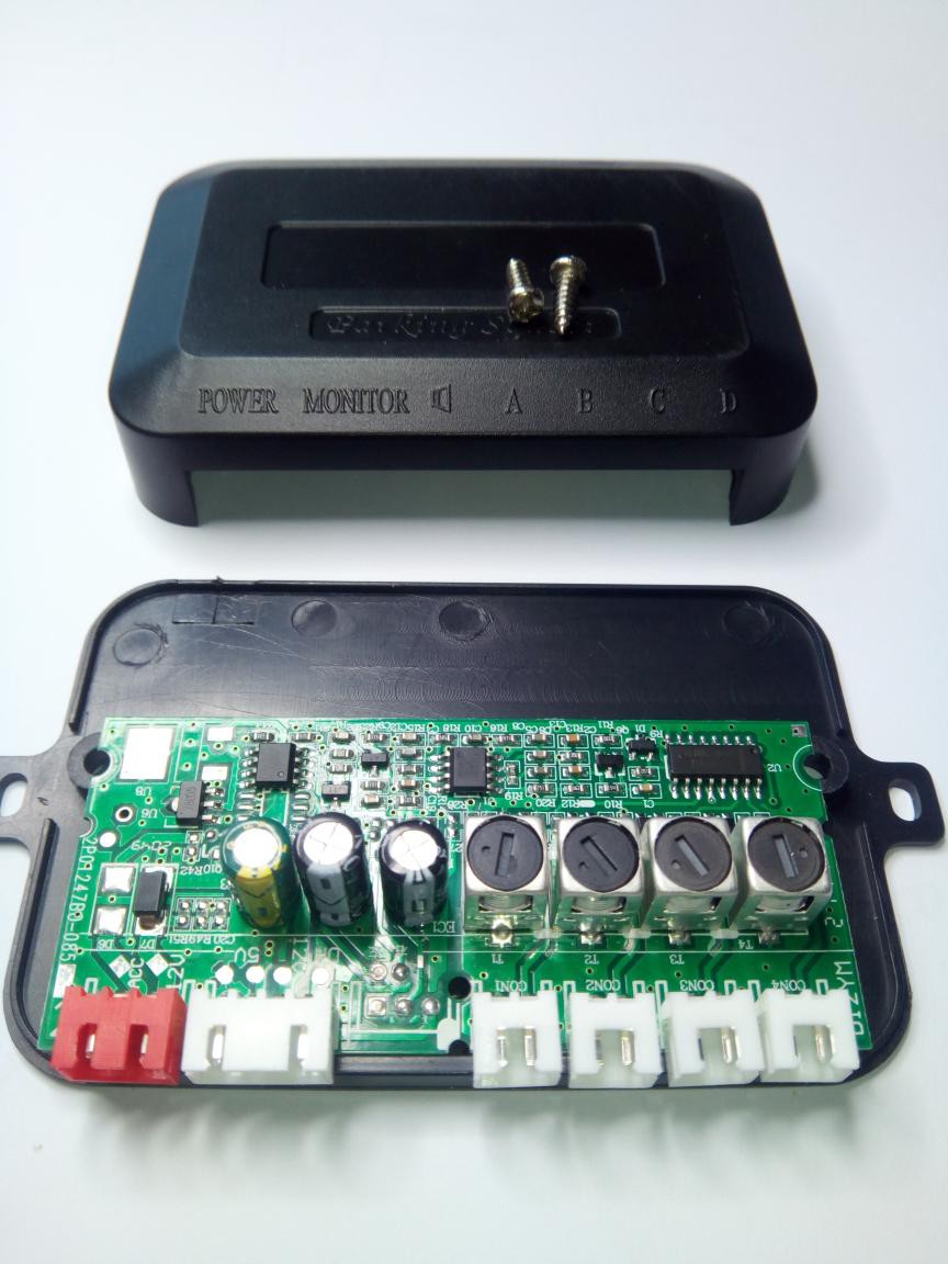
The PCB inside the control box
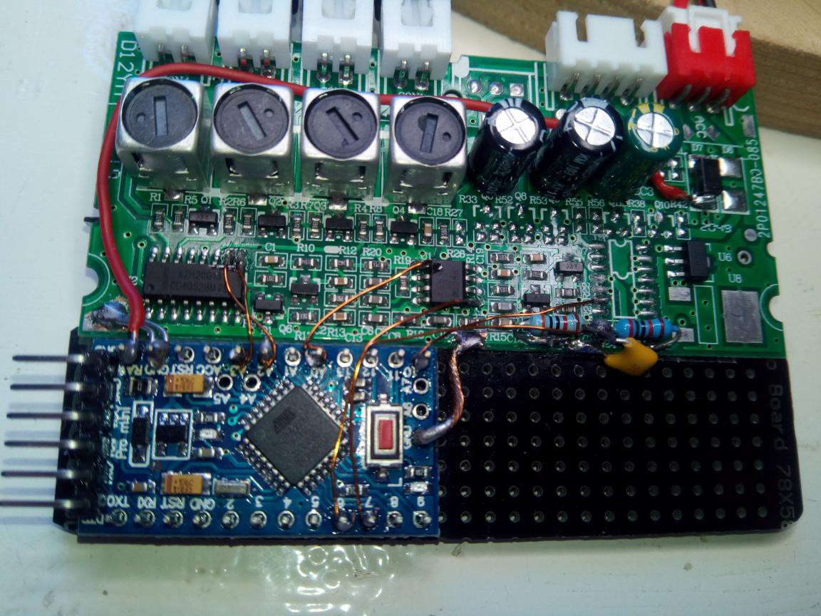
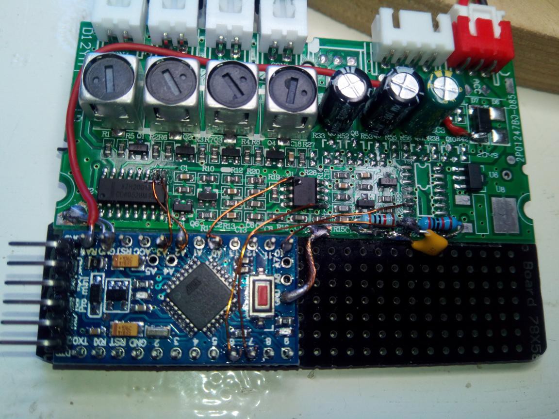
The Arduino Pro mini in place on the car reversing sensor pcb.
Video about how the Arduino was attached to the car reversing kit pcb


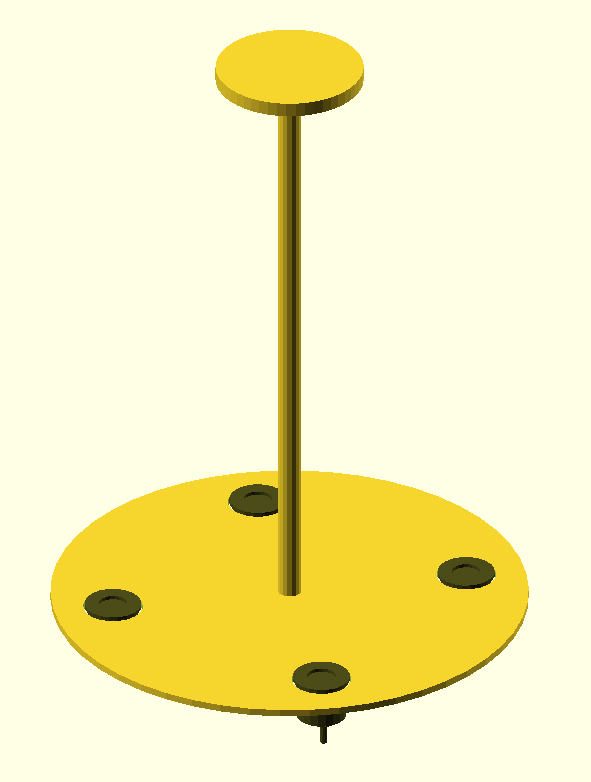
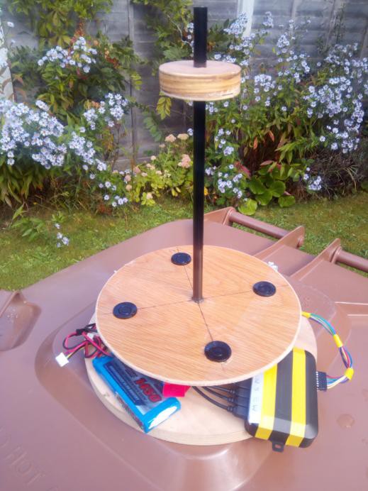
The prototype was designed to be  as simple as possible to make. A 210 mm diameter disc of ply with holes for the transducers at 150 mm diameter (cut out using the hole saw supplied with the kit) and 10mm hole for a central spine to support the 65 mm diameter "echo plate", at the top.  Spine was 10mm carbon rod, but steel or wooden dowel would work just fine. Vertical distance from sensors to echo plate around 250mm.
  • 1 × Car reversing kit A car reversing kit consisting of 4 ultrasonic transducers, a control box and a display.
  • 1 × Arduino Pro Mini Used to drive the transducers and time the pulses
  • 1 × Transducer mount A disc of plywood around 210 mm diameter with 4 holes at 150 mm diameter for the transducers and a 10 mm hole in centre for the spine
  • 1 × Spine 10 mm dia rod x 300mm.. Wood dowel, Carbon or stainless steel. The spine goes through the centre of the unit and keesp the echo plate at a set distance from the base
  • 1 × Echo plate The echo plate is what the signals bounce from. Just a ply disc around 50mm diameter with a 10mm hole in centre for spine

View all 11 components

  • Info on the original car reversing kit MCU​

    kwikius10/31/2021 at 11:33 0 comments

    In reply to https://hackaday.io/project/181677/discussion-169393

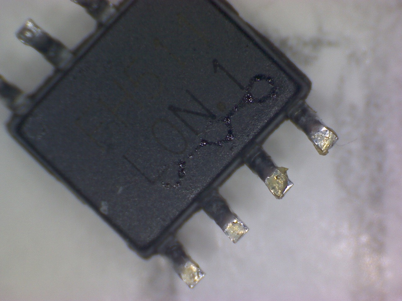
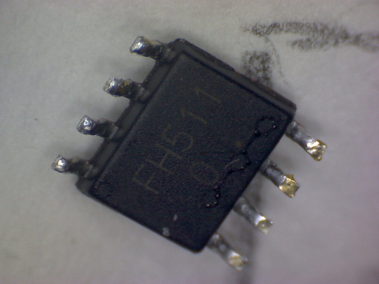
    I  had  another  look at the mcu that I removed from my 2nd version of the car reversing kit and saw it had  chip markings on the underside. (N.B 2 pictures shown as for some reason the light obscures one or other dependent on angle )The markings say:

       FH511
       LON.1

    However I couldn't find anything useful by googling that!


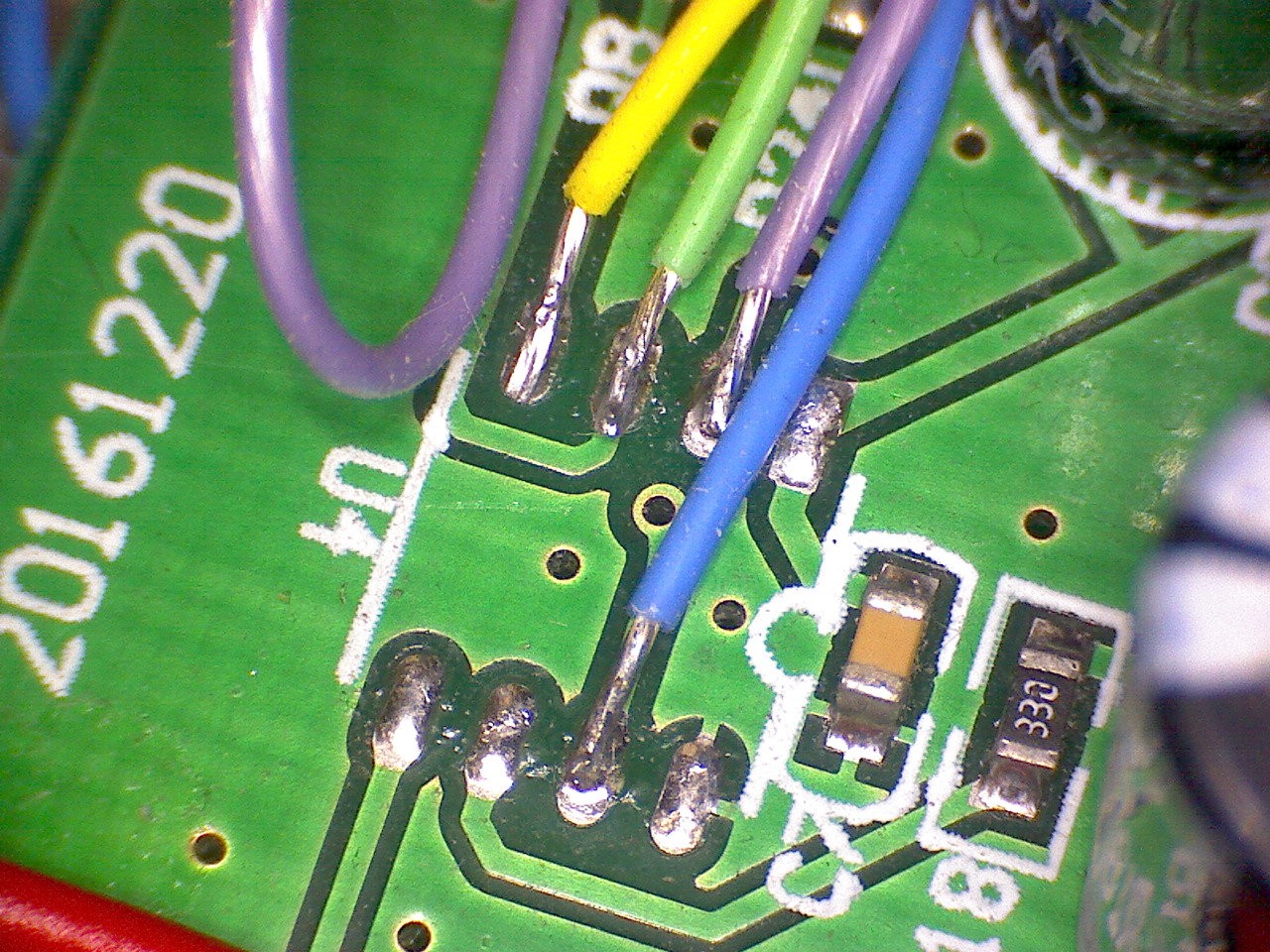
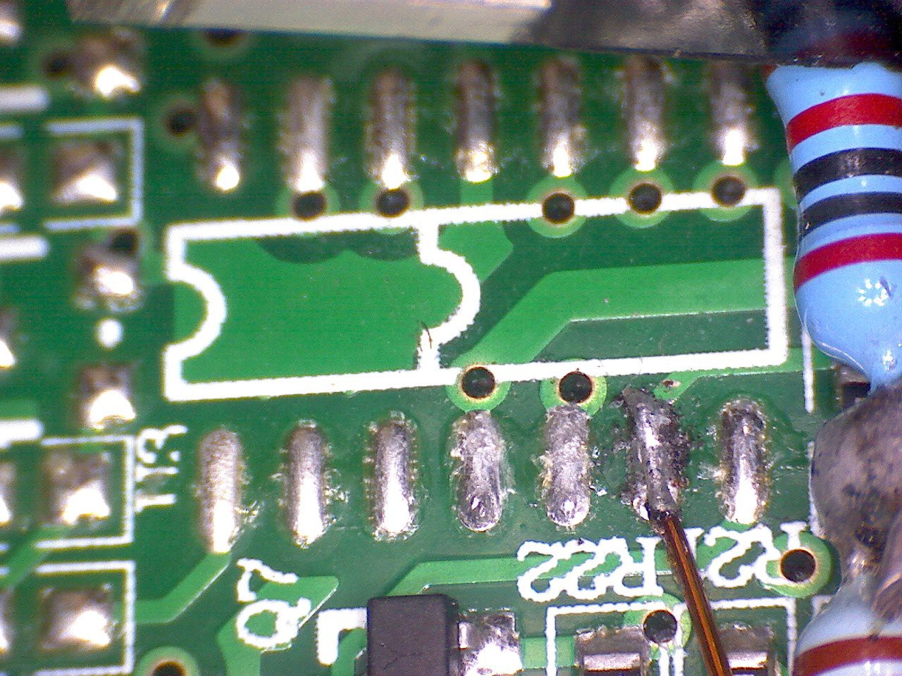
    Here also are some closeups of the two footprints on the 2 different car reversing kit boards I have.

    mcu footprint of first kit1 I bought

    mcu footprint of second kit I bought


    Here is why I think it might be a PIC12

    The original MCU pinout ( based on the 8 pin footprint, but for both boards) v PIC12 footprint. I have only quickly studied the PIC12 datasheet and the pcb so data may be inaccurate!

    pin numberPCB MCU functionPIC12F function
    Pin1
    5V
    5V
    Pin2Transducer address out bit0
    RA5
    Pin3Transducer drive
    RA4
    Pin4Pulse envelope detect
    RA3. T1G Timer1 (16 bit timer) gate, so could accurately capture flight time
    Pin5monitor power? monitor Clk?
    RA2 SCL?
    Pin6
    monitor data IO ?
    RA1 SDA?
    Pin7 Transducer address out bit1
    RA0
    Pin8GNDGND

  • ESP-01 web server schematic

    kwikius10/24/2021 at 16:43 0 comments

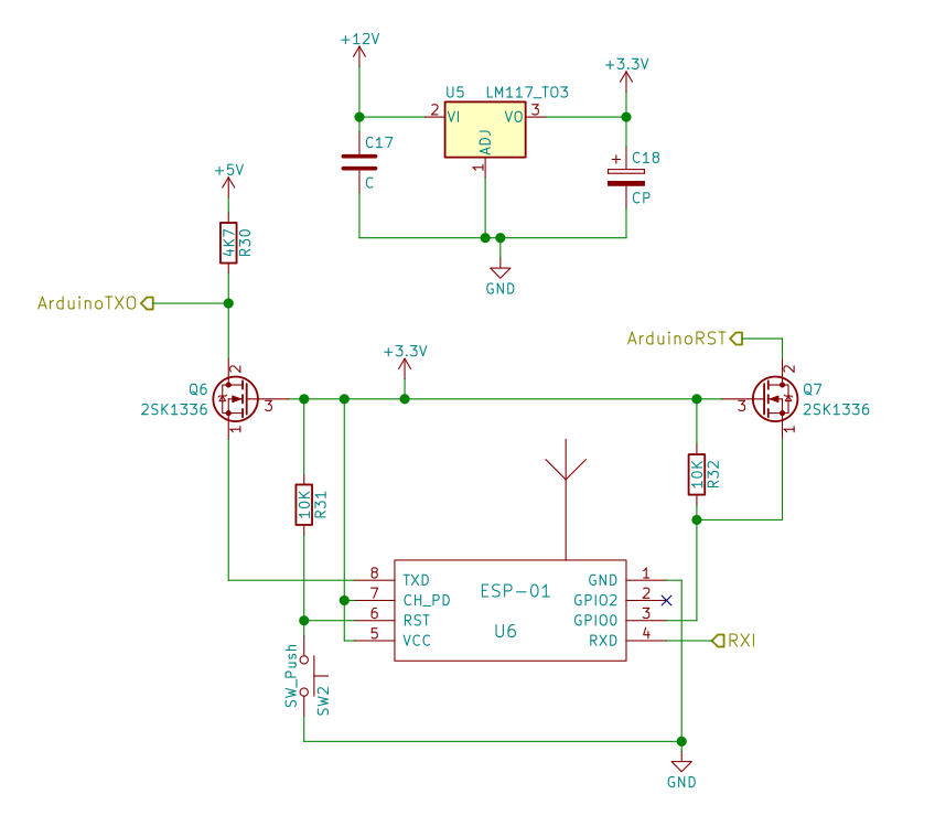
    Schematic for ESP-01 web server allowing the wind data to to be presented in real time on a web page. 


    Transmit out to Arduino is not used at the moment, but would be a nice option, if you can fit it on the board, so one day Sensor could be configured from web interface.  ArduinoRST goes to the Arduino reset line. RXI is the wind sensor data from the Arduino using a voltage divider (not shown here) (2.2K / 3.3K resistors) to drop the voltage to 3.3V. NPN transistors could be used instead of mosfets Q6 Q7, but they would need bases to be connected to 3.3V via (say) 10K resistors. The mosfets were selected because they use slightly fewer components. Voltage regulator should ideally be a TO220 or similar with a good heat-sinking capability as it has quite a voltage drop, when powered from 12V and the ESP-01 does use 100 mA or so when in WiFi transmission mode. R32 is required to prevent the ESP-01 starting in programming mode. Adding a reset button to ESP-01 is always a useful feature too!

    TODO.

    • Do a video describing more details of the circuit and how it fits on the car reversing kit PCB.
    • Update github project with sub-modules to include required web server libraries.
    • Explain how to upload code to ESP-01 etc

    Source code for the web server  here:

    https://github.com/kwikius/ultrasonic_wind_sensor/blob/master/web_server/web_server.ino

  • Add ESP-01 to the hacked car reversing kit PCB.

    kwikius10/12/2021 at 10:06 0 comments

    Update the add on board with ESP-01. Once added to the board Initially I found that ESP-01 had difficulty connecting to the network. I suspect that it is due to noise on the hacked PCB , since connection works fine, if the Arduino is held in reset.  That being the case, I solved the problem by connecting the ESP-01 GPI0 to the Arduino RST input ( via suitable level shift). Now When ESP-01 wishes to connect , it puts Arduino in reset and takes Arduino out of reset once connected. This works well as a solution on the demo board. Once connected the Wifi is smart enough to avoid the noise frequencies and the connection seems to be robust enough for testing and demonstrating.

    https://github.com/kwikius/ultrasonic_wind_sensor/blob/master/web_server/web_server.ino#L105

    TODO: Provide circuit details for ESP-01 and a video of the updated board

  • Use custom polledSerial serial port class rather than Arduino.Serial

    kwikius10/08/2021 at 12:10 0 comments

    The windsensor project is very critical on interrupt timing  to capture the pulse length. Looking at the Arduino.Serial code, it does (of course) use interrupts and even disables the global interrupts during a write. In this application a simple polled serial port will do the job without globally disabling interrupts and without serial write interrupt getting in the way of the envelope detect or zero crossing interrupts, so the Arduino code was modified to use the custom polledSerial class.

    https://github.com/kwikius/ultrasonic_wind_sensor/blob/master/libraries/polled_serial/polled_serial.cpp

  • Added info and video on connecting up the Arduino

    kwikius10/07/2021 at 16:06 0 comments

    Added video and info on how to hook up the Arduino to the extended car reversing kit pcb

  • Use atmega328p internal comparator instead of external comparator.

    kwikius10/05/2021 at 19:35 0 comments

    To get the project working originally I used an external comparator. The comparator is used first to measure the magnitude of the received pulse stream and then to detect zero crossing, by means of positive feedback which moves the trip level between the two levels dependednt on output state

    I wanted to use the internal comparator and eleiminate theat extra component. One problem with the internal comparator is that the outout doesnt go to a pin, which means the traditional positive feedback cant be used. I originally decided to use a spare pin as an output and use it to set positive feedback to the input it in the comparator interrupt, but then I realised I could just use 2 different comparator channels and switch between them in the comparator interrupt.  After some headscratching  and layout issues this is now working well and I plan to stick with this option for the moment. This is actually a much nicer option since it doesnt put any load on the output and samples the filter ground directly rather than a voltage which is around the same level as I was doing with the external comparator. I also would hope that the settling time is much reduced since both of the negative outputs have constant values, one at filter ground and one at envelope detect voltage and the filter output is not loaded at all.

    I also got v2 of the circuit working using the car reversing pcb in the videos, which is much neater than V1, so now need to do a new video about it all.

  • Modify source code to work without requiring main to disable interrupts

    kwikius09/30/2021 at 13:58 0 comments

    Modify source code so that we don't need to disable interrupts. Important since the comparator  is meant to have a lot of positive feedback, which has to be done in software in an interrupt, while only around 6 usec is available to flip the output.
    https://github.com/kwikius/ultrasonic_wind_sensor/commit/9627a261ac55dd3647f3f7eb349310b97648b39b

  • Remove the existing mcu with a hot air soldering iron

    kwikius09/30/2021 at 07:10 0 comments

    The existing 8 pin soic mcu has to be removed. I have a hot air soldering iron for this task. (If you don't have one, then it is possible to remove smd ics by making a u shaped piece of thick copper wire and soldering it to the ic's pins with blobs of solder. Heat it up with a bigish soldering iron and then pull it off with tweezers)

    Also shown in the video is  the piece of proto board, attached to the existing pcb with double sided tape, which works much better than you would think..

  • Cut out and fit proto board to add area to reversing sensor control board

    kwikius09/29/2021 at 10:13 0 comments

    Cut out and fitted the proto board to add some area to the original PCB.

    In the video I mention knitting the 2 boards together with copper wire. To line up the boards for drilling, I  joined the board with doubles sided tape. Once done, I discovered that the result was strong enough just using the tape, which makes life much easier.  Next todo is to remove the MCU with a hot air soldering iron, so will see if the proto board falls off with the heat!

  • Added comparator output to circuit description

    kwikius09/19/2021 at 12:23 0 comments

    Added comparator circuit to circuit description.

View all 11 project logs

  • 1
    Get car reversing kit

    Firstly you will need to get the £10 car reversing kit off ebay. The type you want has 4 ultrasound transducers. You don't need the ones with video cameras etc. Beware that the control circuit will need some modifications which will stop it working as a car reversing sensor, unless you take care to make the modifications reversible.

    Please do understand that at this time, it requires removing some smd components from the board and soldering wires to small traces , so you will need some understanding and experience of electronics and testing and faultfinding of pcbs to be able to make this project.
    Note that your PCB may not be exactly the same as the one here, but I believe the layout of these boards is basically similar, at least on the 2 I have.

    Firstly you need to make an extra piece of circuit board and add it to the existing PCB. Just after doing this video I discovered that the simplest way to join the extra board was with double sided tape, which is what I then did.


    Next you will need to identify and remove the existing microntroller. On both boards this was an 8 pin SOIC chip (though on the second, in a footprint that could also take a 14 pin version), which I believe to be a PIC12. Beware that there is also an 8 pin soic dual op-amp ic on the pcb which is used for the band pass filter. The mcu is unmarked , while the op-amp is marked and surrounded by resistors and capacitors ( I have one marked as a 4558D  and the other as a N5532 ) so if you have a marked ic, hopefully, you can look up what it is exactly to verify it is the dual op-amp


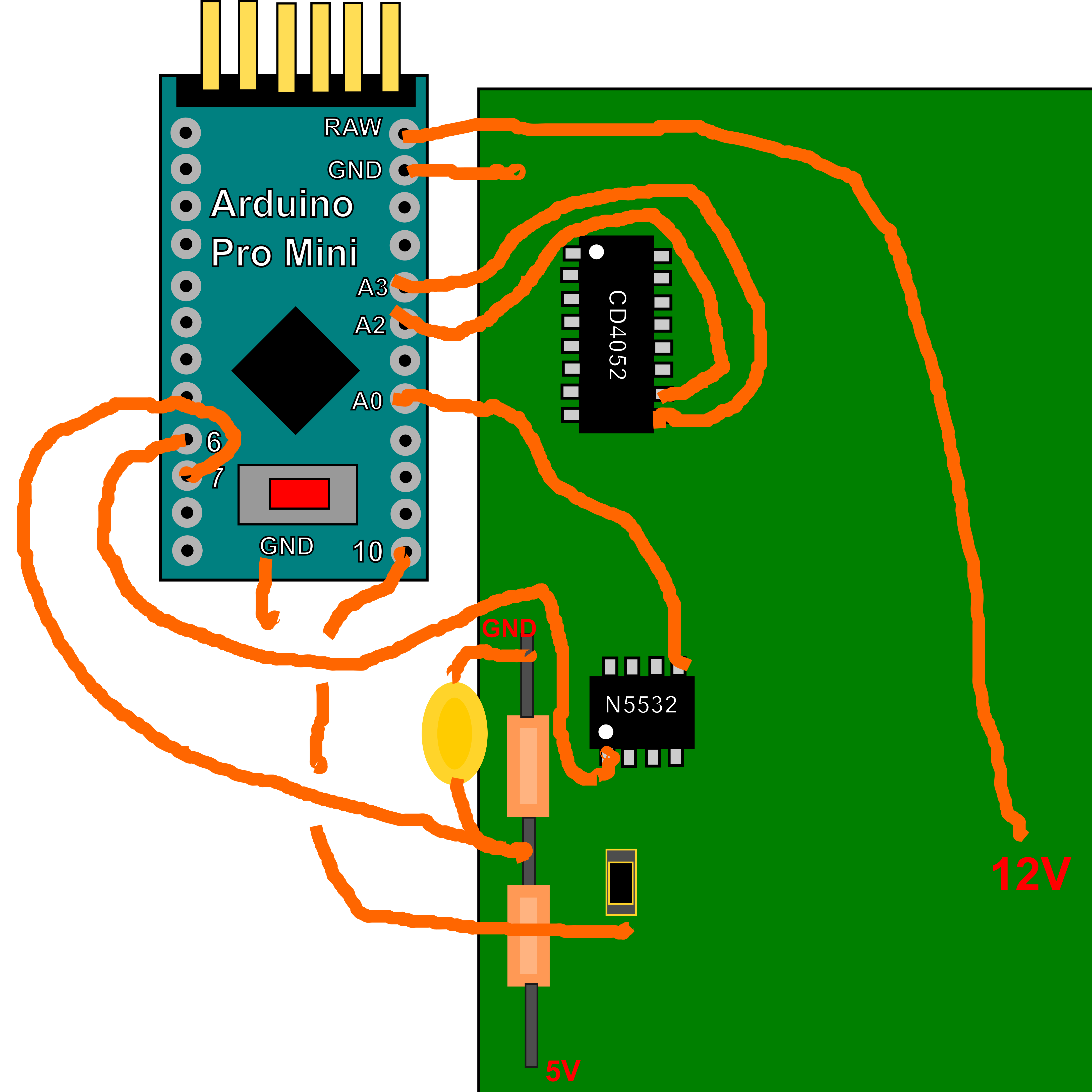
    The Arduino can now be soldered in place on the PCB as shown in the photo. See also the later diagram.
    It is best to start with the ground connections, which should be short and using a decent thickness of wire. I would recommend at least 2 ground connections at opposite ends of the arduino, to the nearest ground on the pcb. You will have to scrape away an area of the car reversing kit pcb to solder to. The resistor voltage divider on the pcb is using a 33k and a 22k resistor with a 0.1uF capacitor to create a voltage of 3v which is the negative comparator input for the envelope detect on Arduino Pin 7. The positive comparator input Arduino pin number 6 ,  is connected to the filter output. The 2nd negative comparator input on Arduino pin A0 is the filter ground, which is available at both the non inverting inputs of the dual op amp. The other connections are from Arduino pins A2,A3 to the 4052 address lines on pins 10 and 9. (Do check the sense of these, so you get the corrcet addressing) . The next connection is the output that sends the transmit pulse. This is connected to the 4052 pin3 via a resistor.  It should be possible to find it on the footprint of the microcontroller we already removed. On both of my versions of the car reversing pcb, it was connected to pin 3 of the microcontroller we removed. Finally connect the "Raw" input to the Arduino, to the 12 V power input (after the reverse protection diode if possible).

    Below is a video describing how to connect the Arduino to the car reversing kit pcb.  Below the video is a diagram of the connections.

  • 2
    Construct the wind sensor frame

    The test frame is very easy to make from ply and dowel as can be seen in the picture

    TODO drawings and details of frame.

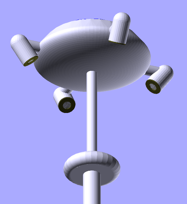
    This is the proposed final long term version of the wind sensor. It is designed to go at the top of a pole.

    The top is intended to take a solar panel from a solar fountain


  • 3
    Connecting up

    https://github.com/kwikius/ultrasonic_wind_sensor/blob/master/ultrasound_arduino/ultrasound_arduino.ino

    Installing and building the project

    Firstly clone the Github Project

    >$ git clone https://github.com/kwikius/ultrasonic_wind_sensor.git

    Next in the resulting project directory, install the quan-trunk submodule using the following command:

    >$ git submodule init  --update  --recursive

    Start the Arduino IDE. Click on 'File > Preferences' and modify the sketchbook location so that it leads to the ultrasonic_wind_sensor directory.
    Close Arduino and reopen.

    When Arduino reopens , click on 'File > Open' , navigate to the ultrasonic_wind_sensor/ArduUltrasonicWindSensor subdirectory and select "ArduUltrasonicWindSensor.ino".

    Next click on 'Tools > Board' and select (AVR boards) > "Arduino Pro or Pro Mini".

    Next click on 'Tools > Processor' and select "ATmega328P(5v, 16 MHz)"

    Now select 'Sketch > Verify/Compile' to compile.

    The code can be uploaded by attaching a serial cable to the Arduino Pro Mini and clicking Sketch > Upload.

    Modifications

    TODO Change the physical dimensions to those of your sensor. Modification of serial protocol  for output to webservere

View all 7 instructions

Enjoy this project?

Share

Discussions

maurizio.butti wrote 10/30/2021 at 16:36 point

Very very nice project. Did you consider the possibility of identifying the existing MCU so that you could just reprogram it without any modification to the he?

  Are you sure? yes | no

kwikius wrote 10/30/2021 at 20:55 point

Hi maurizio,

Great question. Yes. I did look into that.  

The mcu on the board is probably one time programmable, but easily desoldered and replaced (and I think there is some programming circuitry on board the PCB too), but I can confirm that the pinout of a PIC12F will fit the footprint on the PCB.

I think the PIC12L1840 (https://www.microchip.com/en-us/product/PIC12F1840) would be a good choice, but max RAM on the PIC12 is limited to 256 bytes, which is quite a heavy constraint.

I have indeed programmed Microchip 8 bit PICs many years ago

The 8 bit PIC mcus are impressive chips but my problem with these older PIC mcus was that due to the architecture you either needed to use MPASM assembler or a non standard dielect of C. I was learning C++ at the same time I was programming PIC's and was disappointed that I couldnt transfer my C++ libraries to the PIC compiler. I found that the AtMega/AVR 8 bit micros could use vanilla C++ (and  the wonderful gcc compiler) resolved at that time to stop programming in assembler as I was finding that the gcc compiler was doing a good enough job of optimising the C++ code I was writing. After the clarity of writing in C/C++(especially in C++), writing in MPASM assembler was starting to get more and more painful.

The PIC compiler isn't catered for in Arduino , as far as I know, ( for the same core reasons as I found I think)  but Arduino environment provides the lowest barrier to entry, so that more people could make use of the project if it was written for Atmega328

I have also written a version of the source code for the stm32L4 (https://github.com/kwikius/ultrasonic_wind_sensor/tree/master/ultrasonic_driver) and hope also to write some source code for the ESP32 at some point, rather than using the Atmega328 for the timing and using an ESP8266 just as a Web server.

All that said, it would be great to see a version that used an MCU in the original position on pcb, either PIC12 or another MCU

  Are you sure? yes | no

maurizio.butti wrote 10/30/2021 at 23:36 point

Thanks for your detailed answer. I think that if it's a one time programmable MCU it shouldn't have a programming header on the PCB, but I might be wrong. I had some success with "unkown" MCUs in the past (https://ydiaeresis.wordpress.com/2020/04/18/reverse-engineering-a-led-strip-rf-remote-controller/) and I am really curious  about this board. What makes you think it might be a PIC12F? Do you have any detailed image of the programming header? Does this (https://www.ebay.com/itm/353211755957?hash=item523d0fadb5:g:u9wAAOSw~49faajl) item resemble yours?

  Are you sure? yes | no

kwikius wrote 10/31/2021 at 11:42 point

Hi again Maurizio,

Your reverse engineering of the led light strip is very impressive. I also looked at some of your other projects. I especially like the "bristlebot" and I wonder how you could make it steerable, perhaps by a weight that moves from side to side?

https://www.ebay.com/itm/353211755957?hash=item523d0fadb5:g:u9wAAOSw~49faajl does look like my second version of the car reversing kit. Even if not exactly the same board, I think the circuit will be basically the same.

I may be wrong about the programming features on the board. It may just be for I/O to the monitor/display


As to why I think it a PIC12. I suspect the circuit may have originally been published in an electronics magazine and 8 bit PICS were popular back then!. Anyway the footprint fits PIC12 power and ground.

In more detailed answer to your other questions I added a log with pictures and pinout of the mcu https://hackaday.io/project/181677/log/199834-info-on-the-original-car-reversing-kit-mcu


  Are you sure? yes | no

maurizio.butti wrote 11/02/2021 at 22:48 point

It might be a Fansea Fanhai FH511 ? If such a thing does exist, according to this page: https://cxybb.com/article/fanhaidz/117703970. It would be interesting to attach the original MCU to a PICkit...
Or replace it with an ATtiny412 (would 4k flash be enough?)

  Are you sure? yes | no

kwikius wrote 11/03/2021 at 11:16 point

Hi again Maurizio,

I have a PicKit2 and the original mcu. These days running Linux pretty much exclusive, but found a command line app pks2cmd on microchip site that at least runs in wine, though not tried connecting to the part . I think I have some old 8 bit PIC around so will try to hunt them out to connect to them first as I get time and see what happens

As far as using these 8 pin SOIC mcu. Yes the AtTiny would indeed fit power and Ground , so That is another choice to PIC12 for anyone that wants to try hacking the board.

For my wind sensor app the problem on these mcu's is Flash and RAM. Ram appears to be limited to 256 Bytes. My current Atmega328 code is currently using 6.5K of Atmega328 Flash and 187 bytes of RAM for globals. With 256 bytes of RAM not much left for stack variables, so I probably won't be following that path !
That said, the car reversing kit board could be used to make some other stuff such as a 4 direction distance sensor, so all good!

As for the Chinese mcu site, since I don't know chinese I think it would be easier to just desolder it and put on one of the other MCUs that look like they are compatible!

  Are you sure? yes | no

Bharbour wrote 09/20/2021 at 13:42 point

It seems like the sensitivity would be reduced by the sine of the angle between the transducers and the support rod.

  Are you sure? yes | no

kwikius wrote 09/20/2021 at 21:29 point

Sure. I don't know, but if you wish to try the inline version, I am sure the same electronics hardware and software can be used with trivial modifications to the code.

In fact there is a hackaday article from around 2013 about such an inline ultrasonic wind sensor also using an atmega328 https://hackaday.com/2013/08/21/ultrasonic-anemometer-for-an-absurdly-accurate-weather-station.

However I think the inline design has to be much bigger to get the equivalent flight time and is more complicated to build. In practise, it is much easier prototyping with something that can sit on a desk top.

  Are you sure? yes | no

Bharbour wrote 09/20/2021 at 23:05 point

Thanks. I probably will. I need an anemometer for part of another project, and when I finish up some of the stuff I am on now, I am planning on building one.

  Are you sure? yes | no

kwikius wrote 10/12/2021 at 10:25 point

On thinking more about this. Yes in theory, however the effect of the angle is to increase the distance travelled for a given distance between the transducers, which increases resolution  as time_of_flight * clock_frequency of the timer.  In other words resolution can be increased either by increasing timer clock frequency ( limited to 16 Mhz in Arduino)  or by increasing time of flight, by increasing distance between sensors bouncing at an angle as I do etc.

  Are you sure? yes | no

Bharbour wrote 10/12/2021 at 14:08 point

You would get the maximum resolution if the sound path was parallel to the flow direction of the wind. If the sound path was exactly perpendicular to the wind direction, you would not see any change of propagation time from the wind.

  Are you sure? yes | no

kwikius wrote 10/12/2021 at 16:01 point

The accuracy is dominated by the timer frequency.

Assume  timer clock frequency of 1 Hz and a time of flight of 10 s then the resolution is 1/10  or 10% of the flight time

Now assume same clock frequency but  a time of flight of 20 s. Now the resolution is 1/20 or 5% of the flight time , twice as accurate

For a given horizontal distance x between the transducers we can for example double the flight time and hence the resolution by placing the echo plate so that a pulse at 60 degrees to the horizontal hits it so the height of the echo plate y = tan 60 deg * (x/2).

You can carry on increasing the angle and hence the flight time, but after some time the device gets very tall and the pulse received gets very weak. Also for high wind speeds the difference in angles between forward and reverse flights becomes significant in affecting accuracy of the calculations

  Are you sure? yes | no

Bharbour wrote 09/19/2021 at 19:15 point

Nice project!

I have seen ultrasonic anemometers done with the transducers facing each other, and I understand how they work. With your implementation, it seems like the wind is perpendicular to the sound travel. How does it work? What am I missing?

  Are you sure? yes | no

kwikius wrote 09/20/2021 at 09:04 point

Thanks.

The transducers are pointing straight up on the prototype but the sound beam does diverge quite a bit and so enough will head in the right direction to bounce off the smaller ply disc at the top of the rod (which I call the "echo plate") and be detected by the receiver at the opposite side.

An advantage of having the transducers pointing straight up is that the transducers aren't in the airflow, which can cause issues with turbulence on the traditional "in line" style of ultrasonic wind sensor.

It was done this way for a simpler reason ;  it is very easy to make using simple tools! As you can see its just a piece of ply with holes drilled (using hole saw supplied with car reversing kit!)

  Are you sure? yes | no

Similar Projects

Does this project spark your interest?

Become a member to follow this project and never miss any updates