 mircemk
This time I will show you how to make an Arduino-powered Tic-Tac-Toe robot, which will provide you an excellent game experience.
Visit my sponsor PCBgogo for all your PCB needs, 10% OFF NOW!
https://www.pcbgogo.com/promo/from_MirkoPavleskiMK
The game is played on a small whiteboard that is covered with transparent packing tape that will make it very easy to erase the board between games. For better visual effect, communication with the robot is done through a small TFT color screen.
This is an Open Source project called "TICO – Tic-Tac-Toe Arduino Robot" and detailed documentation can be found on the author's website:
https://playrobotics.com/blog/tico-tic-tac-toe-arduino-robot-documentation/
If you decide to make it yourself, share your questions and join the conversation on the Tico Facebook group:
https://www.facebook.com/groups/890278848555627
Unlike the original design, I made the mechanical part from a PVC board with a thickness of 3 mm which I processed with a scalpel.
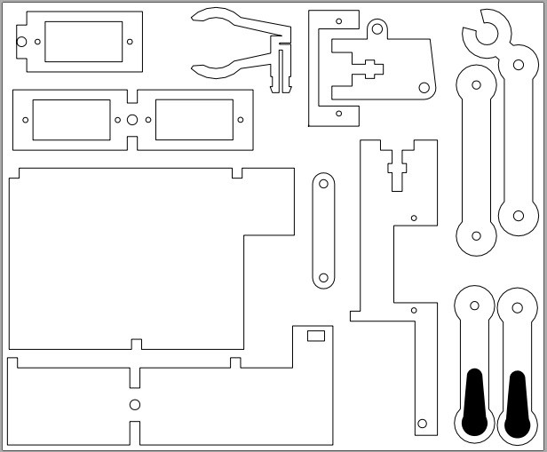
In fact, I made this part for one of my previous videos that described a project called "Plotlock", when I still did not have a 3D Printer. The initial design of Tico was inspired by this Plotclock project, and Parts of the Plot clock’s code is used in Tico’s code. Of course, it is much better and easier to make if you have a 3D Printer, and .stl files are given on the page.
The game starts when the robot clears the board first, then draws the frame and marks the first move. After that, the human player marks his move on the board, and also on the remote controller, or on the Arduino serial monitor depending on the settings in the code. When someone wins, the robot marks it on the board and on the screen with a message.
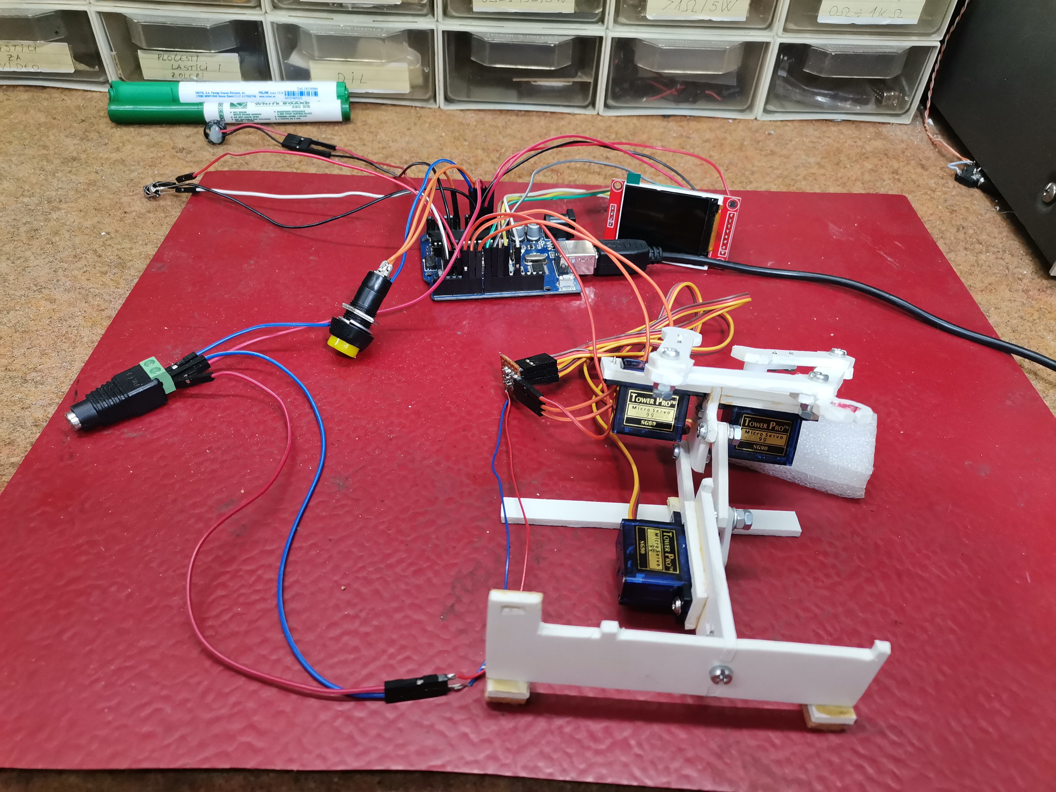
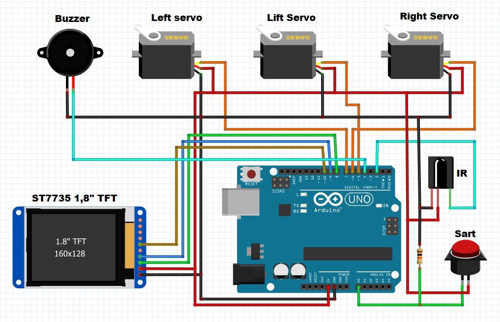
The electronic part of the device is very simple to build and consists of several components:
- Arduino Uno microcontroller
- Three cheap 9 grams servo motors
- 1.8 inch TFT color display
- Buzzer
- Button
- and Ifra Red receiver
We will first show the case when we enter our moves through the Arduino serial monitor. To do this, we need to modify the next line of code:
#define SERIAL_MONITOR_MODE true
The robot can also mark our moves. It is given through the section:
#define DRAW_HUMAN_MOVE true
If we want to enter our moves with Remote Controller we need to make the following code modification:
#define SERIAL_MONITOR_MODE false
To find out the codes specifically for your remote controller, I made a small program that you can also download at the link provided.
As you can see in the video the Robot can not boast of any great Intelligence, but this is an Open Project and I hope that in the future that part will be improved.
 Javier Isabel
 Red Chili
 Jithin Sanal
Hi - just posted on Hackaday
There is absolutely no need for “AI” to calculate moves. Given only 3 unique openings (all others are just a rotation) I have a state machine with just 109 states to cover all moves. The machine knows how it will respond in each state so many states are unreachable. That would be easy to fit into Arduino [edit] flash. Happy to share and help, but needs some work to convert to code.