Close
0%
0%

Palm Pilot Keyboard Bluetooth Conversion

Converting a Palm Pilot Portable Keyboard into a Bluetooth keyboard using a TinyPICO ESP32

Public Chat
Similar projects worth following
The Palm Pilot M500 series of Personal Digital Assistant was released in 2001. One of the many accessories in the ecosystem of the time was a folding, portable keyboard that actually felt OK to use, especially when compared against some other silicone mat type, rollable, portable keyboards. Repurposing a Palm Portable Keyboard (PPK) was the subject of a 2015 Hackaday post (https://hackaday.com/2015/04/04/repurposing-a-palm-portable-keyboard/), but I found that my keyboard had a much finer pitch between the contacts and I also wanted to add bluetooth capability.

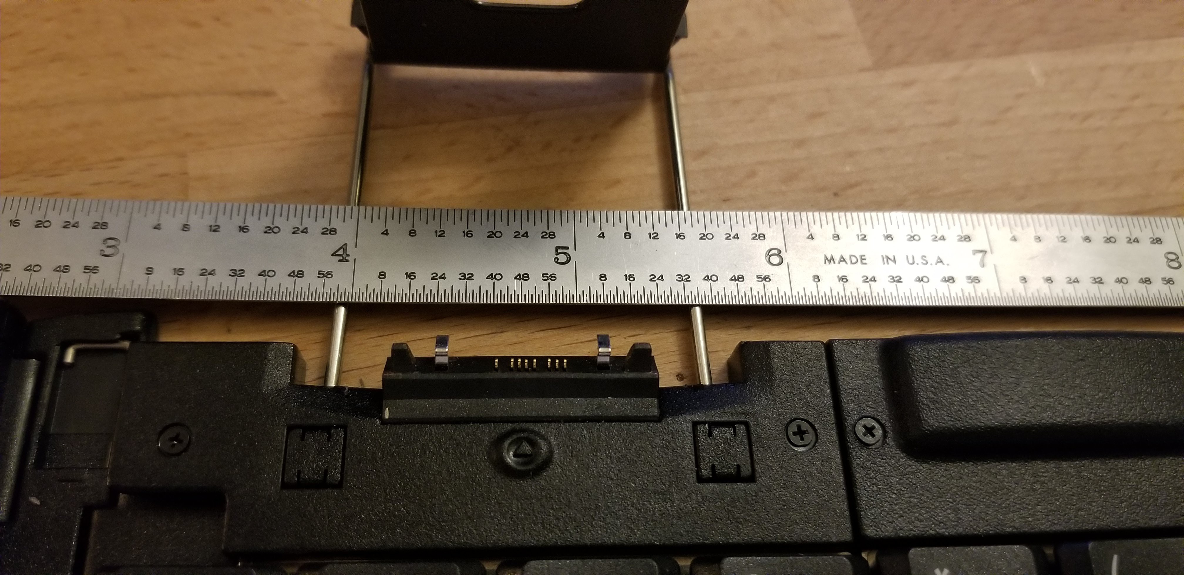
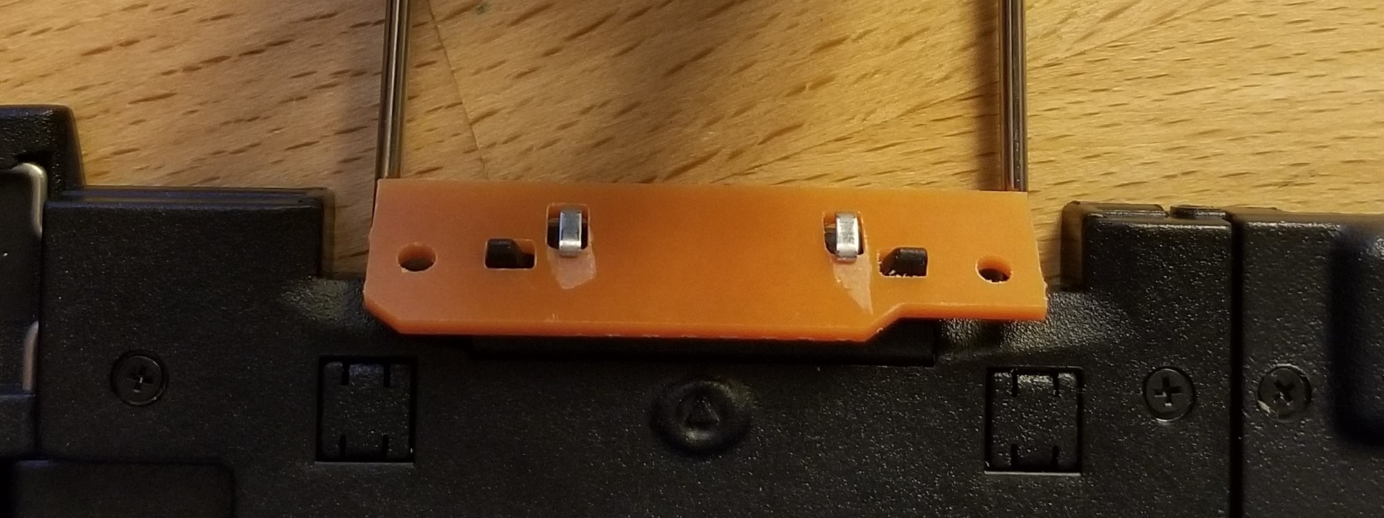
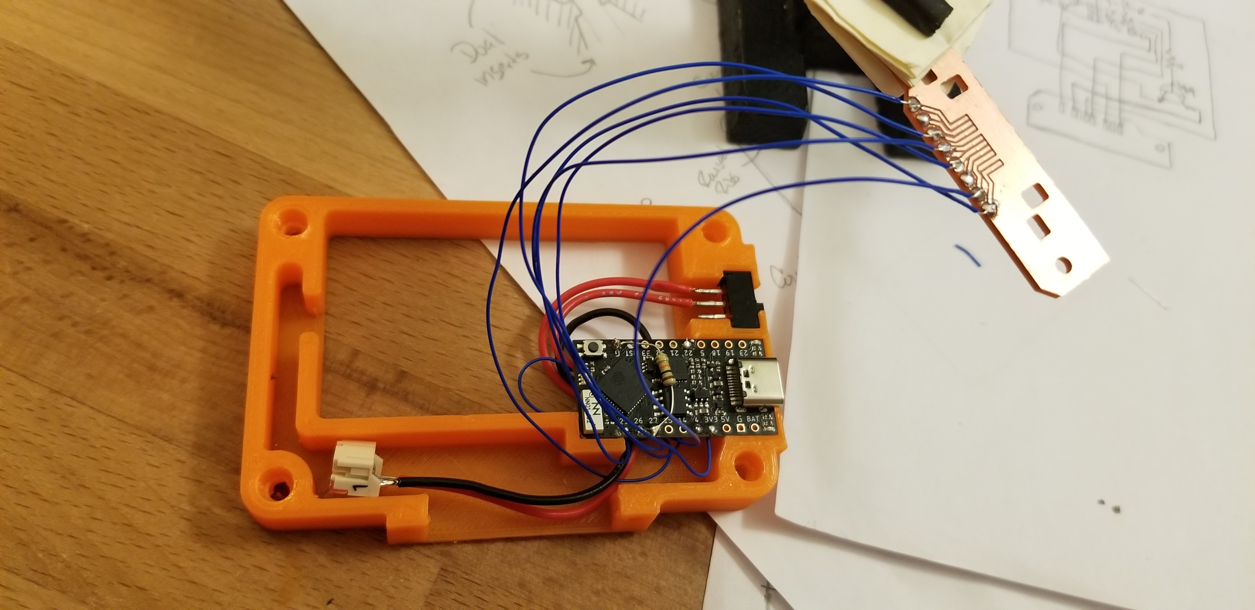
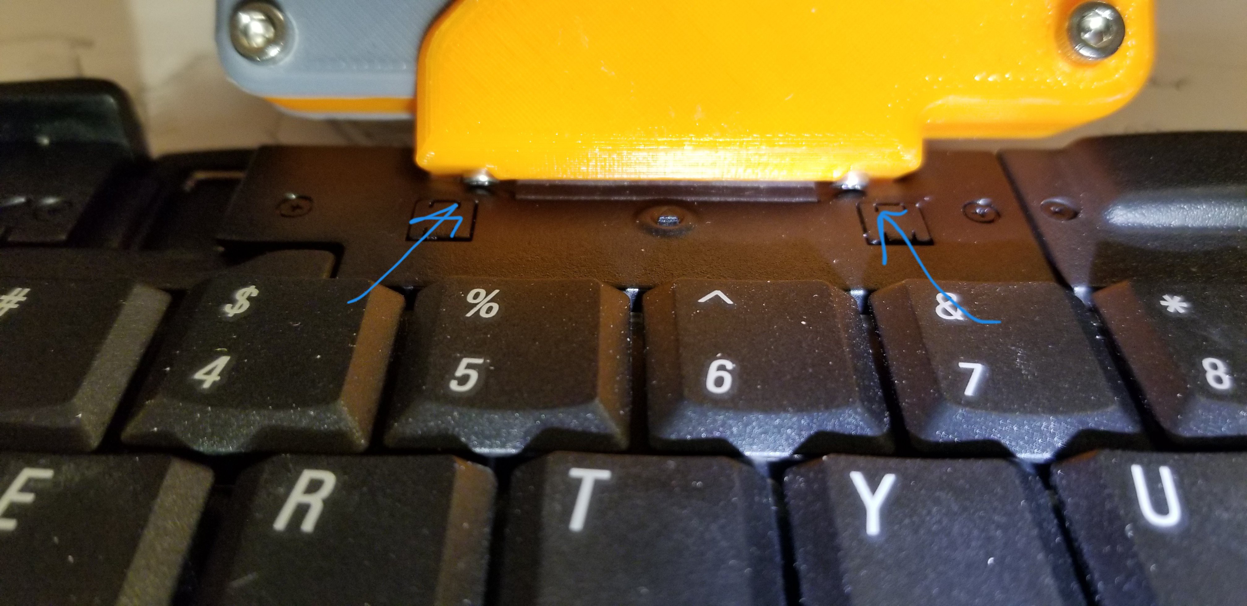
I started from [cy384]'s excellent repository for an Arduino Pro Micro based adapter for a PPK. Unfortunately, I found that the pinout on my keyboard was different and had a much finer contact pitch (0.8mm!). I ended up needing to fabricate a small PCB to break-out the pads to something hand-solderable. The PCB also allowed me to mechanically interface to the alignment pins and metal retaining clips originally intended to keep your PDA attached. I made several 3D printed mock-ups of the mounting interface before committing to dimensions for the PCB. 

The PCB was machined using my MPCNC with some single-sided copper clad board. I was extremely happy that the machine could attain this level of precision, but anything finer and I'd likely send it out for fab. I used some cheap 30 degree V bits ( https://amzn.to/3krEvZt) for the engravings and some slightly-less-cheap 1/32" end mills for the mechanical hole interfaces and the board cutout (https://amzn.to/3EH6EUz). Each was run at ~6mm/s and 0.15mm depth per pass, though the engraving really only needed 0.08mm depth to get through the copper. 

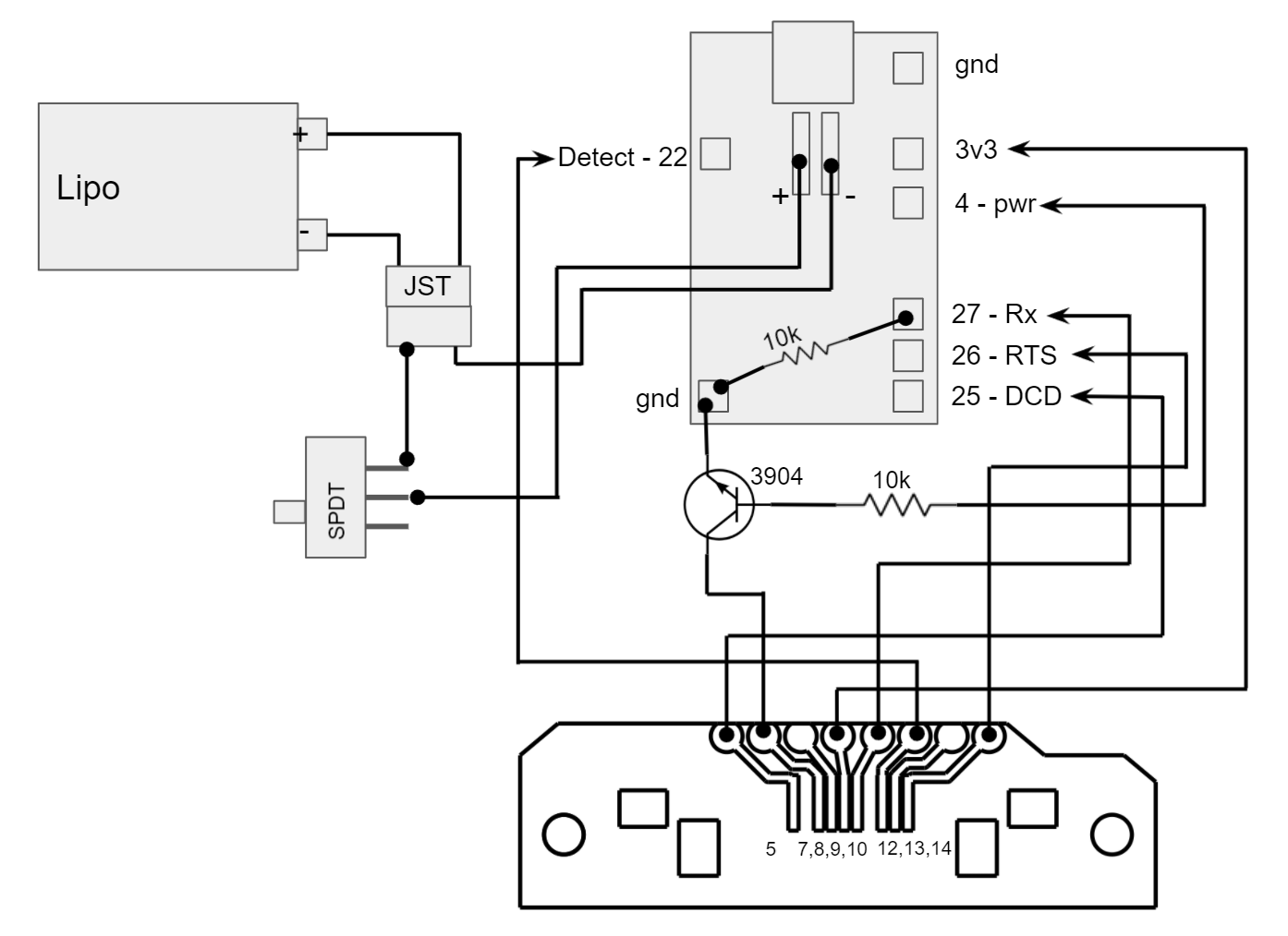
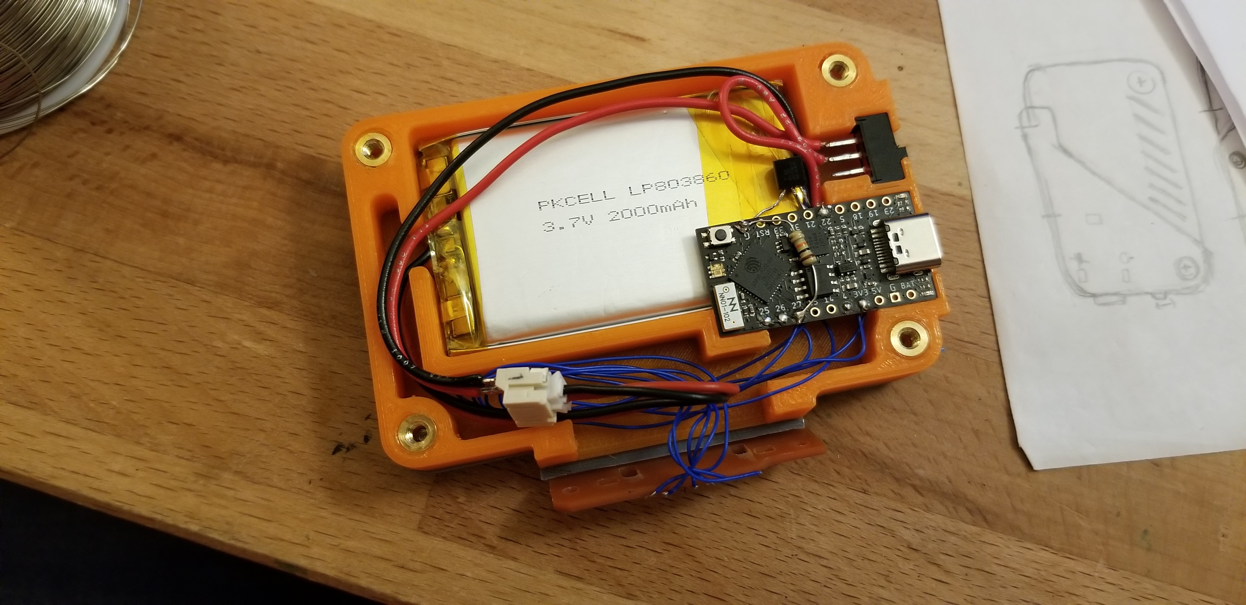
Next up was the programming. I was able to find a pinout reference for the M500 series of Palm Pilots, which saved a lot of reverse engineering (https://pinoutguide.com/dev/Palm/m500/). I added my new pinout assignments, replaced some of the libraries with ESP32-friendly versions, changed some handshake routines, and gave it a go. It turns out, the ESP32 cannot act as a hardware HID, only a bluetooth HID. This is resolved in the ESP32-S2, but I was not aware of that. I was able to connect to my tablet and it was time to move on. 

I added some battery management, monitoring, and reporting (via the RGB LED) to the code. Now, on startup, it will blink blue until the keyboard is booted up. Then, it'll blink every 5 seconds with a color representing the battery state (red up to 15%, yellow up to 30%, green above 30%). Every 5 minutes, the battery voltage is checked using an internal analog pin, and then the reading is compared to an array of increasing voltages spaced at 5% increments. This allows any arbitrary voltage curve to be checked against and edited with relative ease. The remaining battery percentage is simply 5*(array index). This percentage is used to set the heartbeat color and is reported to the hosting bluetooth device. 

  float batVolt_lookup[] = {3.27, 3.61, 3.69, 3.71, 3.73, 3.75, 3.77, 3.79, 3.80, 3.82, 3.84, 3.85, 3.87, 3.91, 3.95, 3.98, 4.02, 4.08, 4.11, 4.15, 4.20};
  float batVolt = 0.0; //volts
  int batLevel = -1; //0 to 100 (percent as int)
  
  batVolt = tp.GetBatteryVoltage();
  for (int n=0; n<=21; n++) 
  {
    if (batVolt < batVolt_lookup[n])
    {
      batLevel = 5*n; 
      break;
    }
  }

The complete code can be found here: https://gist.github.com/T3hWombat/889ddb50863ac82e46ec27c594a203cb#file-ppk_ble-ino-L3

In theory this should be a fork of [cy384]'s code, but I'm really bad at git, and I didn't want to break anything so gist-it-is!

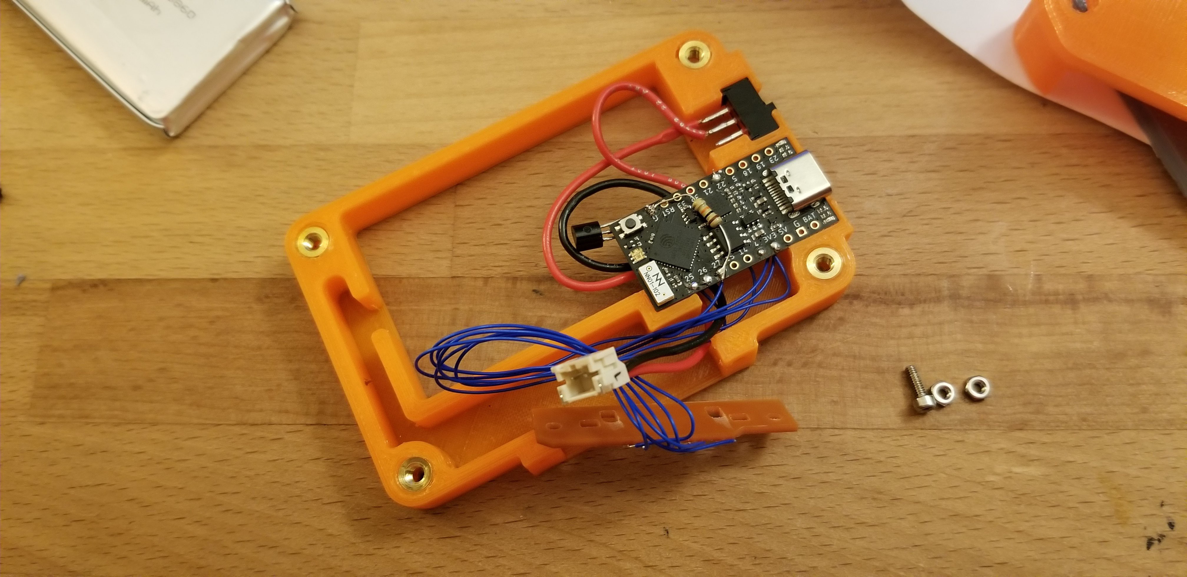
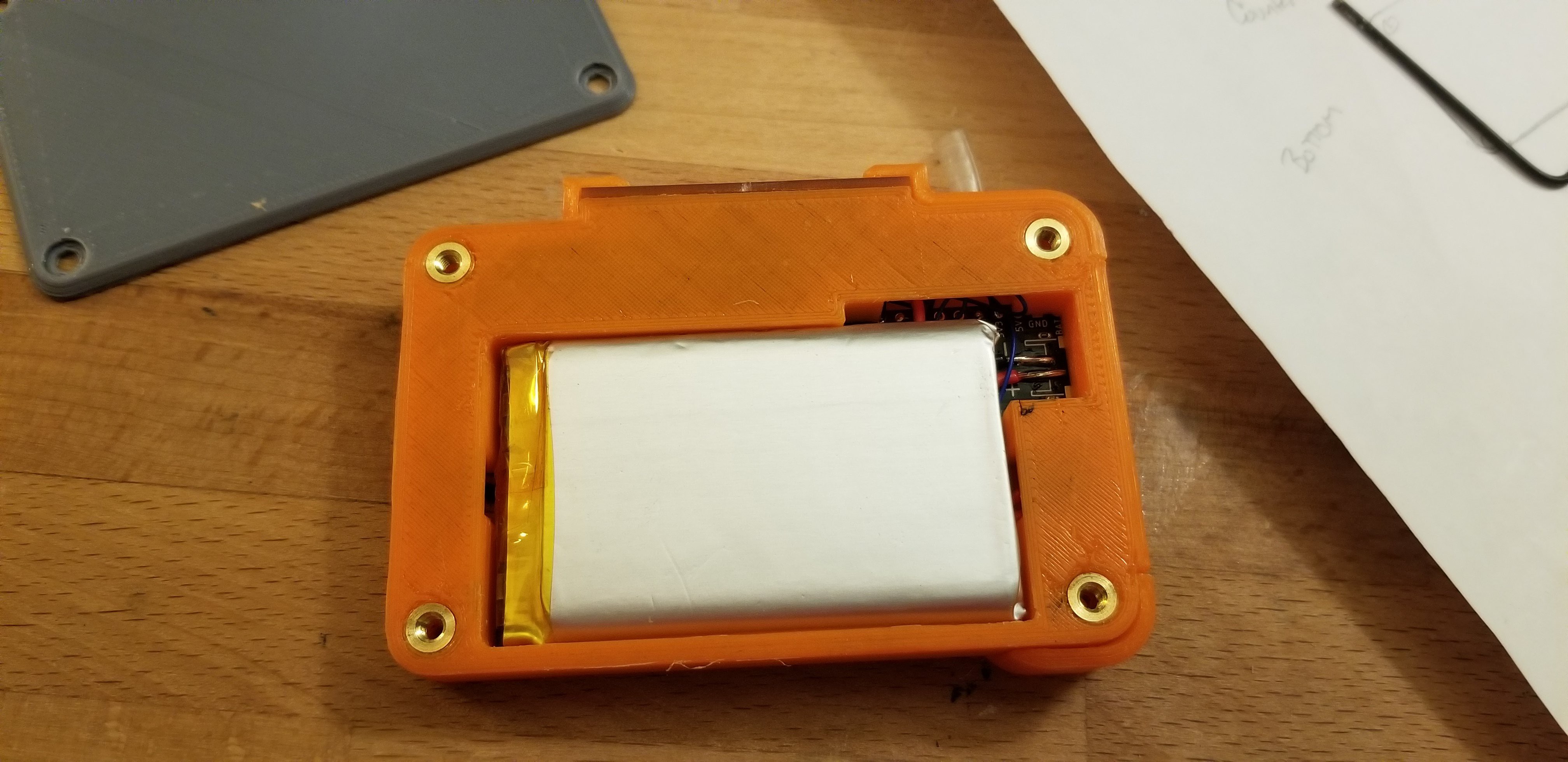
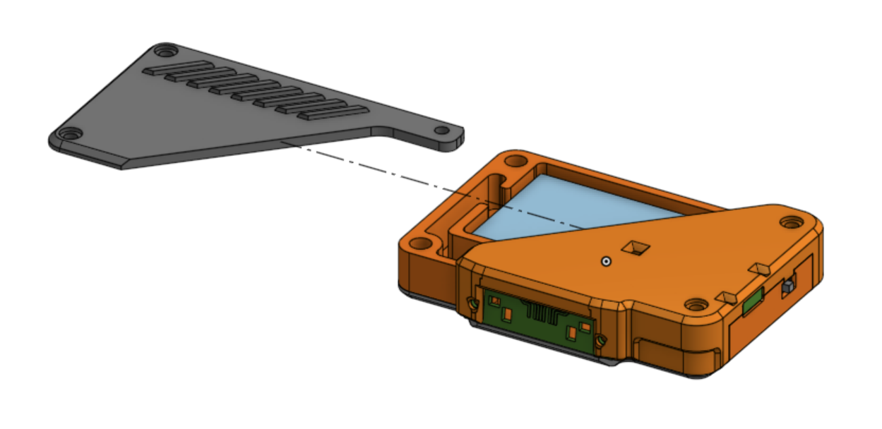
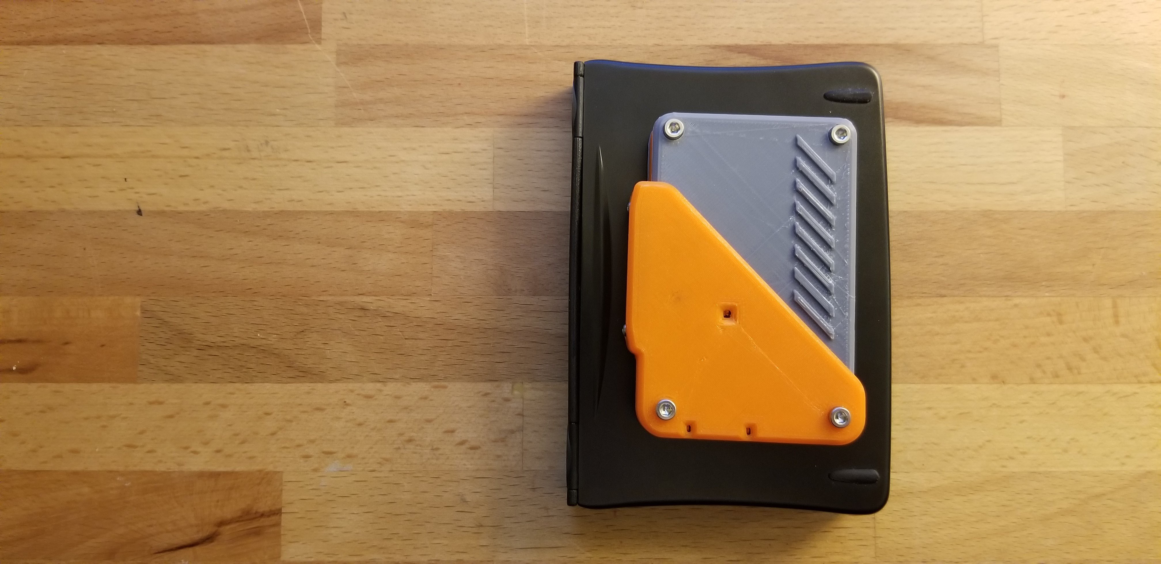
Next up was the enclosure, which was (of course) 3D printed. I split the enclosure into 4 separate pieces to allow for appropriate print orientations without using supports. Unfortunately, this took some 5 or 6 iterations to get right - I kept having mechanical interference problems with the awkwardly shaped keyboard socket. 

The STLs can be downloaded from thingiverse: https://www.thingiverse.com/thing:4973314

My CAD designs can be viewed and copied from OnShape:

https://cad.onshape.com/documents/5fbfe51195bf188388e559c1/w/5058cbc034fa7652620829a5/e/ac3999bc0bc2e0288bf5ca2c

Some interesting notes from the journey: 

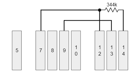
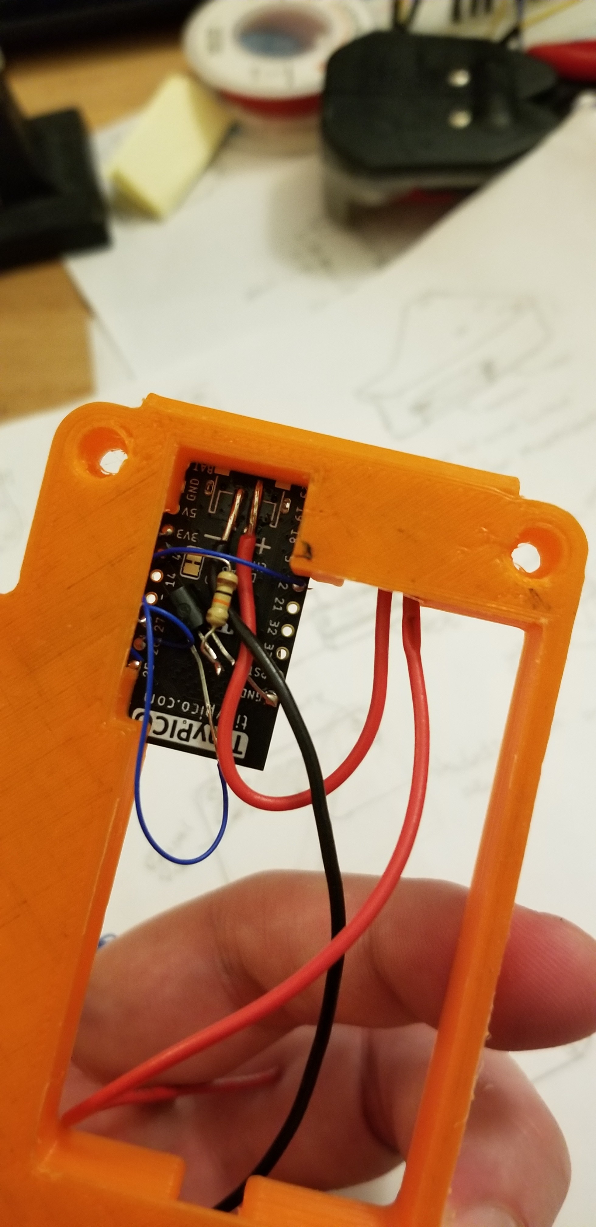
  • A pull-down resistor is required on the Rx line. I thought that the ESP32 included pull-down resistors that could be enabled via software, but I was not able to get this feature to work, so I added an external pull-down. 
  • [cy384] powered his keyboard directly from an IO pin, which is generally frowned upon....
Read more »

x-zip-compressed - 4.18 kB - 09/30/2022 at 04:28

Download

Standard Tesselated Geometry - 574.59 kB - 09/22/2021 at 00:07

Download

Standard Tesselated Geometry - 295.00 kB - 09/22/2021 at 00:07

Download

Standard Tesselated Geometry - 448.91 kB - 09/22/2021 at 00:07

Download

Standard Tesselated Geometry - 201.35 kB - 09/22/2021 at 00:07

Download

View all 6 files

View all 12 components

  • Gerber Files Uploaded

    Christian08/27/2022 at 20:06 0 comments

    I've uploaded a zip archive of the gerber + drill file needed for the adapter board. The cutouts in the board are smaller than the OshPark minimum limit, so you'll need to use a different service. My original prototype board was 1.3mm thick, and I had to scrape away some of the board backing so it would clip into the palm pilot. I'd recommend a 0.8mm board if possible or be prepared to cut away some of the board thickness with an Xacto blade. 

  • Go Forward Plan

    Christian10/05/2021 at 18:24 0 comments

    At this point, the project is functionally complete... but there are some firmware improvements I intend to make going forward:

    • Monitor the "peripheral detect" line and detect a keyboard disconnect event, then attempt to re-connect when detected again. Currently, the module must be fully installed onto the keyboard before powering the module on. Once the keyboard handshake is complete, the LED changes from blue to green/yellow/red (depending on battery state). I'd like for the handshake to wait until the device is connected. I had this kindof working, but the handshake would begin instantly and would fail because I couldn't finish plugging the device in fast enough to connect all the pins. A short one or two second delay should fix this. 
    • I'd like to make the heartbeat LED fade in and out instead of pulsing. The LED is surprisingly bright and - let's just say that the current version encourages touch typing. If you're looking at your keyboard be prepared for a photon assault. This too should be relatively straightforward to implement. 
    • I would like to implement a low power sleep mode. Currently, the keyboard is kept awake the entire time and constantly draws power. The TinyPICO also has some built-in deep sleep modes that I'd like to take a look at. The Hardware and Electronics reference guide has some details about the Keyboard's low power mode and how to enable and recover from it.

View all 2 project logs

  • 1
    Pinouts and Wiring Diagram

    I was able to find a Hardware and Driver reference document that explained the pinouts, handshaking protocols, and low power sleep mode handling for some Palm Pilot Keyboards that were similar but not the exact model of keyboard that I had on hand (specifically model P10802U, user's handbook for reference). 

    Hardware and Driver Reference: http://www.splorp.com/pdf/stowawayhwref.pdf

    My particular keyboard only had pins 5, 7-10, and 12-14 present at the interface. 

    PinName
    5Hot Sync (DCD)
    7Gnd
    8ID (leave open for keyboard)
    9Vin (3.3V)
    10RxD
    12Peripheral Detect (tied to gnd by keyboard)
    13CTS (unused in handshake, but tied to Vin by keyboard)
    14RTS


    I did some continuity and isolation testing on the keyboard pins and I found that pin 12 (peripheral detect) is tied to pin 7 (gnd), which is consistent with the documentation. I also found there to be about 344kOhms between pins 7 (& 12) and pin 14. Additionally, pin 13 (CTS) is tied directly to pin 9 (Vin). During the handshake, the palm pilot should look for CTS to go high, indicating that the palm pilot should be ready to receive data. Since the keyboard leaves CTS as always-high, it isn't actually needed in the handshake procedure... we can just assume it's always high. 

    Now, to wire this up to the TinyPICO. Most of the GPIOs can be used, but I tried to avoid any pins that were shared by the USB port or any pins that were unpredictable at startup. 

    TinyPICO
    Pin
    NamePPK Pin
    4Power Enable7 (via 3904 transistor)
    *see schematic
    22Detect12
    25Hot Sync5
    26RTS14
    27RxD10
  • 2
    Circuit Board, Wiring, and Soldering

    I used 30 AWG solid core wiring for each of the signal connections, but 22 AWG stranded wire for the battery connections and power distribution. The TinyPICO has pads ready to go for a JST battery connector, but it faces the same direction as the USB, and since I overlapped the TinyPICO and the battery, there wasn't enough space to solder the JST connector directly to the board. Also, I wanted to include a power switch on the device between the TinyPICO and the battery. I soldered the JST connector to the TinyPICO interface with a couple inches of wire in between. 

    In the above picture, the 3904 is directly underneath the TinyPICO - I ended up relocating it after this picture was taken. There isn't enough space under the TinyPICO to fit much more than the resistor. 

    A note about the PCB: The thickness of my single-sided copper clad was 1.35mm, which was slightly too thick to fit underneath the flexible metal retaining hooks on the keyboard. I had to flip the board over and scrape away some of the fiberglass with an XActo knife. I'd estimate at least 0.3mm was removed. 

    Just give the board a couple of fit checks before you start soldering to it. 

    Tuck the wires over the top and around the back of the PCB as closely as you can. There isn't much clearance between the solder points and the 3D printed cover (installed later). 

    There's a boss on the 3D printed cover that will press down on top of the big, main chip on the TinyPICO, so make sure you route the 10k pulldown resistor AROUND the chip and NOT OVER it. 

  • 3
    Mechanical Assembly

    I used a soldering iron to press the brass inserts into the 8  threaded interfaces on the 3D printed "frame" (4 inserts each side). 

    Pop the switch and the TinyPICO into place and tidy up the wires. Insert the battery from the bottom side of the bracket. Make sure the switch is in the OFF position, and plug in the JST connector. 

    Install the rear cover. 

    Flip the assembly back over and tuck the wires into the channels as best you can. Set the M2 hex nuts into their respective slots.  

    Hold the circuit board roughly in place and slide the enclosure lid (the lid half WITHOUT THE RIBS) down over everything. This lid will sandwich the circuit board in place. Carefully insert the 2x M2x10 button head screws through the cover and the circuit board, and into the pre-placed nuts inside the frame. 

    Most standard socket head screws will not fit in this location. Standard M2 socket head screws stick out too far and will prevent you from installing the module. Trust me, I tried: 

    :-(

    The last step is to slide in the other half of the lid sideways, being careful not to pinch any of the wires. The thicker half of the case needs M3x10mm screws. The thinner half takes M3x5mm screws. 

    Et Voila. 

View all 3 instructions

Enjoy this project?

Share

Discussions

Similar Projects

Does this project spark your interest?

Become a member to follow this project and never miss any updates