 Colin Maykish
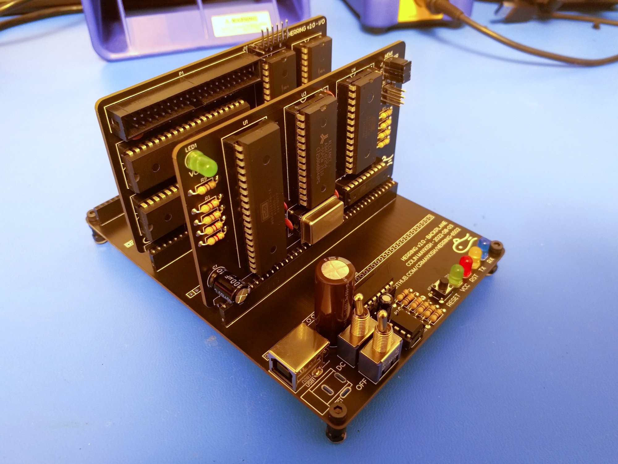
I finally got around to ordering the next iteration of PCBs. There are enough changes here that a new major version number was justified. As discussed in the log, the main focus was on consolidation and usability improvements.
The backplane now has a 555 timer for a power-on reset circuit and a MCP2221A USB-to-serial chip on board. This is the change I'm most excited about. There is now a single USB connection on the backplane for power and serial. The Tx and Rx lines are routed on the bus so one of the ACIAs on the new I/O board can supply the console over the USB-serial adapter. Using USB with nothing but through-hole components is pretty cool. I've left a DC connector on there just in case. One of the switches selects which power source to use, USB or DC.
The existing components boards have not changed significantly in function, but I have condensed the CPU, ROM, RAM and a decoder GAL onto one board and two of both the ACIA and VIA chips onto another. Tons of I/O packed into just two boards. This frees up the backplane slots for other experiments.
As always with a redesign, I have bugs:
Without thinking, I connected the reset line of the MCP2221A chip to the same reset connection that the CPU uses. Unfortunately, resetting the USB-serial chip seems to force it to enumerate on the host PC which kills the serial connection. This is annoying as every time the CPU reset button is pressed the serial console dies. The solution is simple: just disconnect that reset line from the CPU reset. It has an internal pullup and seems unnecessary for normal function. For now, I just removed the reset pin from the IC socket so that it doesn't make contact. The reset button now works as expected, keeping the console alive while the CPU resets.
The other issue is more of a mechanical problem. The first socket on the backplane is too close to the other components and the capacitor is a bit too big so the component boards won't fit. Oh well, at least I combined the other boards, so I've got plenty of open sockets left to use.
I'll fix both of these problems in the next version of the PCB, but I'll do some more testing to make sure there are no other changes.
Discussions
Become a Hackaday.io Member
Create an account to leave a comment. Already have an account? Log In.