 Dave Collins
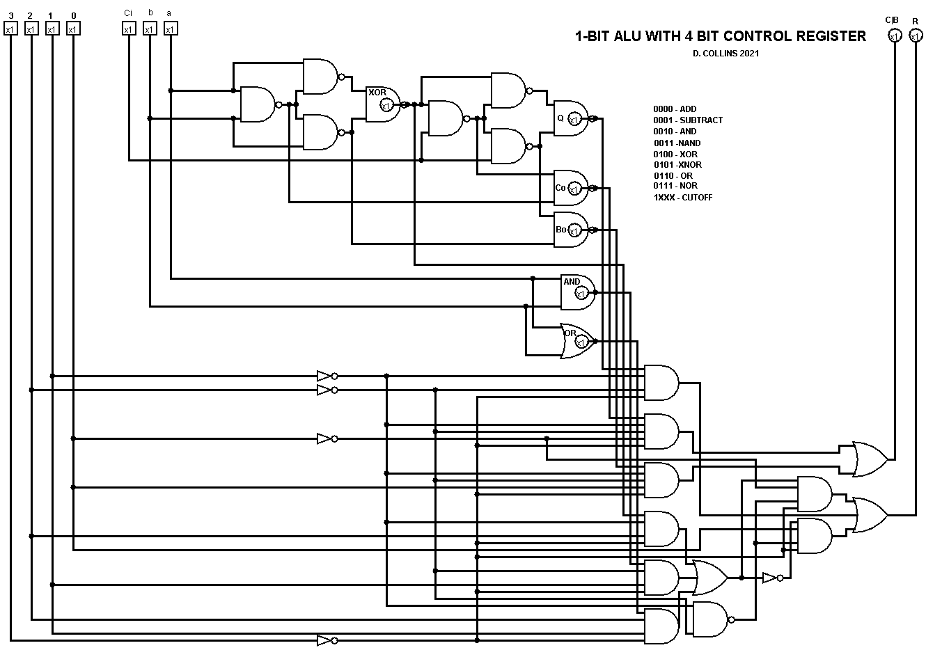
The ALU is mostly completed; I have built the proof of concept so now is on to building the ALU and it's 4 bit decode (actually 3). I was able to omit an additional XOR GATE (a savings of 1 whole package!). This was done by taking the results of the first XOR gate from the full adder. I'll be the first to admit Its not the best design but I was shooting for as few gates as possible to try to keep the package count under 4. I made a major decision that I'll be using diodes to make some of the OR gates; as it's going to be VERY complex otherwise. The 3 bit command word selects between ADD WITH CARRY, SUBTRACT WITH BORROW, AND, OR, XOR, NAND, NOR, AND XNOR. I opted for leaving in NOR and OR, as they can be used in place of LOAD 1 or LOAD 0 as the result is predictable based on the data bus. This allows me to omit this instruction in the command register for memory operations. The remaining 4th bit puts the whole ALU circuit into cut off, this is convenient because the memory and bus control register will also have a 3 bit command word; though the forth bit will be used to cut off the control register in a low state (as opposed to a high state cutting off the ALU). I will more than likely microcode this using an eeprom but for now next will be the D flip flops for the Results register, and the CB Flag.
Discussions
Become a Hackaday.io Member
Create an account to leave a comment. Already have an account? Log In.