These days, I am interested in building a small-scale hydroponic system that can also fit on my desktop to observe closely its performance in growing a plant. I had no previous experience in hydroponics so, I started searching on the internet and decided to go with the flood and drain system. Since it would be an experimental setup, I had to think about my budget to save money. I thought it would be great if the entire planting pot could be 3D printed. I would also definitely need a water pump to pump the nutrient solution. It would be great if the pump could be powered by a USB charger. So I came up with these requirements.
It should be:
- small to fit on a desktop.
- cost-efficient to save money.
- a resemblance to the actual system, which can also be scalable.
- powered by a USB charger or maybe a power bank. Let me rephrase this as low power.
- preferred to be 3D printed.
How will it work?
In summary, the system will work as follows. There will be two tanks piped together. The first tank will hold the plant; the second will be the reservoir which will contain the nutritious water. There will be a controller which will track the time. For example, once every hour during the day time controller will pump the nutritious water from the reservoir to the first tank containing the growing plant and will flood the tank. After and during the flooding, water will be drained back into the reservoir tank. The controller will follow a different watering scheme for day and night time. Therefore, a light sensor will be utilized by the controller.
Discussions on advantages and disadvantages
As far as I have searched from the internet and having watched several hours of YouTube videos, I can list several advantages and disadvantages of this system over other hydroponic systems. Here you can find a brief list of mine.
First, advantages:
- Simple and easy to operate.
- Low power to operate. This is because the pump is only operated a few times during the day.
- Enables enough oxygenation of the roots
- Low probability of fungal growth
- Maintains a lower root temperature
Disadvantages:
- Requires separated tanks for plants and nutritious water
- Probability of low dissolved oxygen in the nutritious water
- Probability of algae growth due to the low dissolved oxygen
Designing the system
Before doing anything, first I searched for a pump on the Internet and I found this:
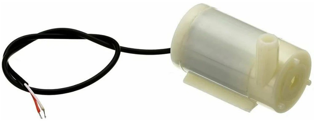
There were some variations of this pump, but the cheapest one was this which I could manage to buy.
Some listed properties of the pump are:
- 80 to 120 Liter/hour flow rate
- 2.5-6 V DC operating voltage
- 130-220 mA operating current
- 40-110 cm hydraulic head
- 56mm length, 24mm diameter
- suitable for water
After a few hours spent on modeling, I have designed this planting medium. This design consists of two tanks which are top and bottom. The bottom tank preserves nutritious water and pumps, while the top tank contains clay pebbles and the plant. A form of clay which is called "hydroton" can be used at the top tank, or cocopeat can also be used instead.
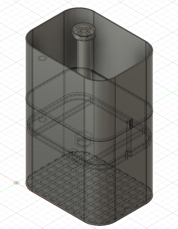
Water and air pipes:
To equalize the reservoir pressure with the outside pressure while the pump is operating, we need a small air pipe whose one end is connected to the reservoir and the other end is open in the air. This small pipe also serves a second function. Although it is not guaranteed to work if the growing media is over-flooded with water, this pipe can drain the excess water to the reservoir. The second and the larger pipe is the water pipe which is directly connected to the pump. At one end of this water pipe, there is an elbow connected to direct and adapt the dimension of the pump outlet. At the other end of the tube is a chimney that is used to keep pressurized water flowing downwards into the growing medium rather than spouting it.
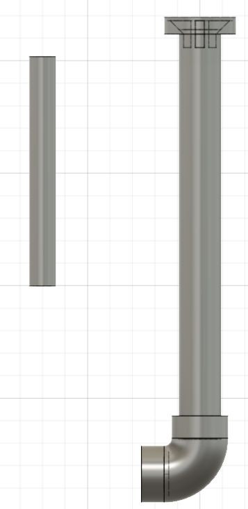
Dimensions:
Here is a drawing of the growing pot. All dimensions are given in mm. From the A-A section in the drawing, the top part slides into the bottom part. There is a small pocket that bends inside the top part for pump cable routing. The pump's inlet faces the bottom of the reservoir. In this way, the pump can suck and pump all the water until the last drop.
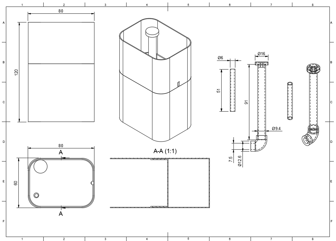
The controller
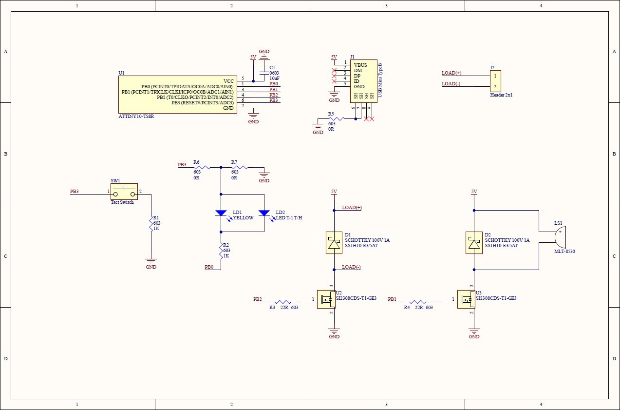
Those who are familiar with the Attiny10 would definitely know that this microcontroller has restricted sources. It has only 4 multiplexed I/O ports. These ports can feature a timer, ADC, clock, and IO functions. For these reasons and more, Attiny10 fits beacon applications. Attiny10 features an internal 8Mhz clock, which varies by the ordering options. This eliminates many external components from being used and simplifies the circuit. Here, I further eliminated the light sensor and preferred to use an LED both as a light sensor and an indicator. I have used a Trench Mosfet to switch on and off the pump motor of course, together with freewheeling diodes. The best way to catch attention and give varied information to users, a loudspeaker or a buzzer, will be the best choice in addition to the low power consumption. Of course, there may be a need to collect some user inputs. This could also be possible by adding a button. I can't see any other low-power input device other than a button, which is great! This button can be used to generate an interrupt and wake the Attiny10 from sleep. To sum up all, here is a shortlist.
- button for man to machine interface
- LED for a machine-to-man interface, also a light sensor
- buzzer for a machine to man interface
Using LED as a light sensor is already a studied and well-known subject; thus I only need to tweak some parameters to have a working sensor. Here you may find some resources if you are interested [1].
Prototyping the controller:
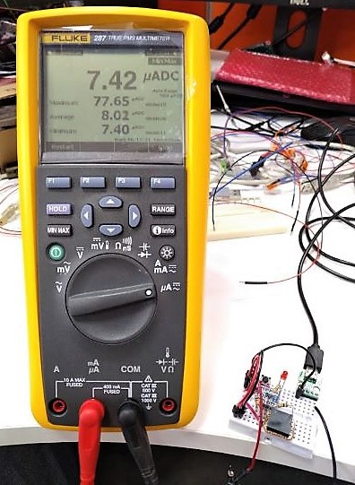
Before going any further to PCB drawing and freezing the schematics, I started prototyping the controller circuit on a breadboard. In this way, I have also started to see problems earlier that will occur during the integration with the system and start developing code early before freezing the schematic. Utilizing a circuit on a breadboard, I fully tested my code and circuit to a grade where I felt confident or I got bored testing. The next photo was taken while I was measuring several conditions of power consumption. To place Attiny10 on the breadboard I have used a sot23 breakout board. Most of the time I used my computer's USB output for powering the circuit, but sometimes I also used a power bank and USB chargers. By doing this I observed that my LED light sensor was sometimes affected by this change. This is due to the noise generated by the power sources, especially the chargers, when they are operating under light loads like my low power circuit. This was a bottom note.
From schematics to PCB:
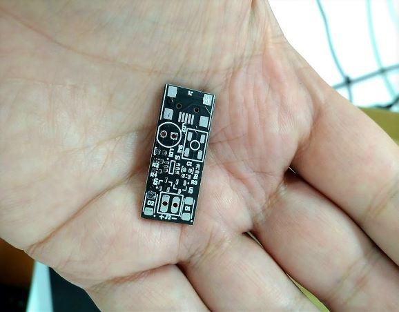
After extensive testing for days and an eagerness to continue, I started drawing a schematic. Now, the hardest part of drawing a schematic is determining and selecting components. I started searching for reachable, cheapest, and reliable parts from the internet and finally I came up with a BOM list. From this point, things move faster because the rest are technical issues such as drawing a proper footprint for the part and creating a symbol or so. You can find my BOM list below, but I must warn you, because some parts I have bought were not listed with a manufacturer, and they are no-name. I think the most attractive and exciting part is waiting for the PCB to be delivered. Down below, in the photo, you can see my precious but low-cost PCB.
Software development and operation:
To develop software I have used the "microchip studio" environment. There are many Attiny10 projects available on the Hackaday pages. I am highly inspired by the Ben Heck Hacks videos related to the attiny10.
Currently, I am not utilizing the user button but will definitely use it in further developments. I have uploaded all my code, drawings schematics, and project files to my GitHub page. My 3D design files are also uploaded to my Thingiverse page.
Programming:
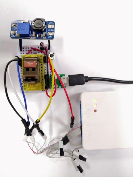
To program Attiny10 I used a socket programmer and Atmel-ICE Programmer. Since I have been using these tools for other applications, I haven't invested extra money in them. Since I have been using the reset pin as an IO, I used a boost converter to get 12V from 5V supply from USB for high voltage programming if reprogramming is needed after setting the RSTDISBL fuse.
Designing a case for the controller board:
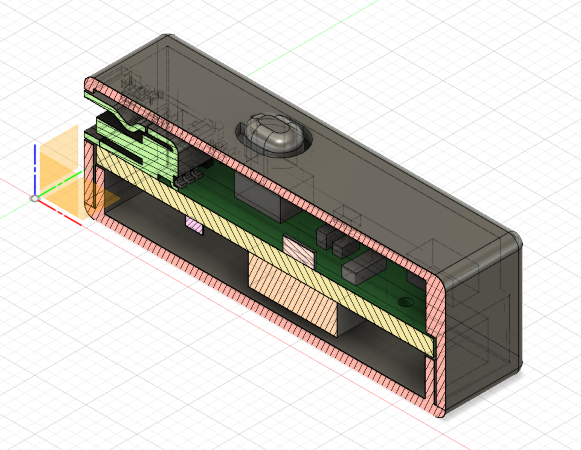
When I submitted my order to produce a PCB, I started working on a case for the controller board. I exported a STEP file from the PCB tool and then started building my case design on top of it. It was an easy task, but the tricky part with the box was the button section. This button should be extended to the top face of the case and should be flexible enough to be pressed. So, I came up with the solution below as seen in the drawing. I have used a single contact point to hold the button on the case. Another important point is that it must be printed with a transparent filament for the light to enter and exit the case.
Further improvements
The good part of the software is its neverending improvements. One can always come up with an idea to implement on software. I have already started making a list of further improvements related to the button function.
- It can be used to start manual pumping.
- It can be used to increase or decrease the pumping intervals.
- It can be used to switch between newly defined modes
References
[1] P. Dietz, W. Yerazunis, and D. Leigh, “Very Low-Cost Sensing and Communication Using Bidirectional LEDs,” in UbiComp 2003: Ubiquitous Computing, vol. 2864, A. K. Dey, A. Schmidt, and J. F. McCarthy, Eds. Berlin, Heidelberg: Springer Berlin Heidelberg, 2003, pp. 175–191. doi: 10.1007/978-3-540-39653-6_14.
 Engin
Engin