 Dimitar
Hello everyone,
I wanted to give you some info about how RoEnDi came to be.
About 7 years ago I started work in automotive sector and more specifically embedded systems. ECUs for seats, dashboards, infotainment, diagnostics for end of line testing, you name it.
One of the projects was for a climate control unit. Just like this one:
 It was very convenient having the buttons and the rotary encoder combined. Unfortunately the parts that could make this happened were not available to the general public.
Fortunately last year I was going through the new parts list of a major electronics part distributor and lo and behold I see the same encoder I have see a few years back.
At first I wanted a simple project, just a breakout board, maybe some resistors and caps for debouncing the encoder outputs. But would you get my board or the encoder and hack a few parts together on a breadboard?
Yeah right. So I did what any normal engineer would do... over engineered the simple rotary encoder.
I wanted a USB, UARTs DAC, ADC, SPI, sleep modes and battery charger for mobile use. I was thinking if making a board compatible with the STEMMA QT to make it easier for the people to integrate it.
I have chosen ST microcontrollers first and foremost because I know them really well. I have dealt with them on numerous occasions. They have bootloaders for Arduino IDE and kind of tick all the features I want. But all cannot be good. They a hard to get nowadays and not the cheapest. Something to think about next time.
The first go of the board was with the STM32L412 good little MCU.
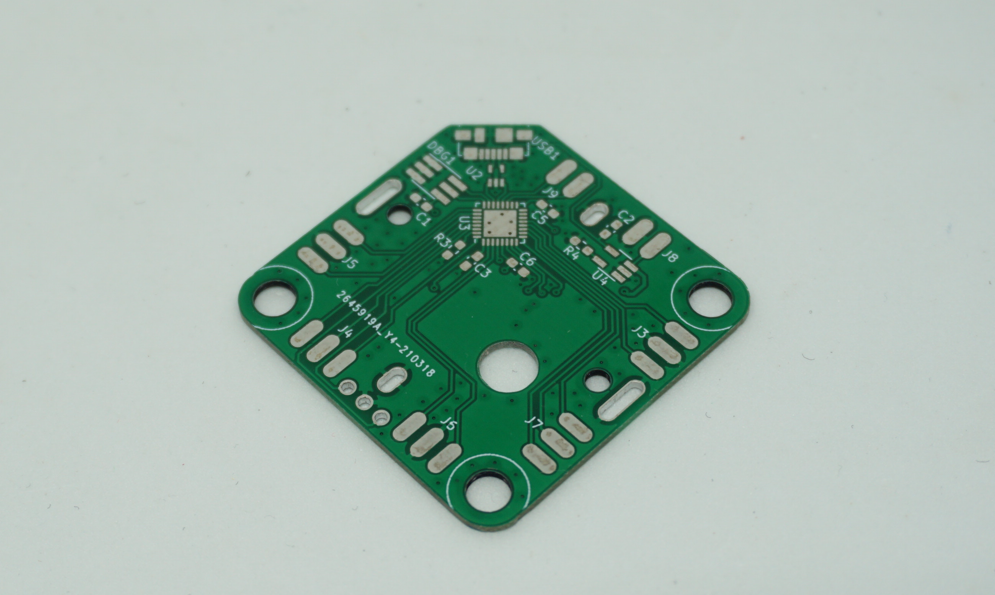 On the back there was a RGB LED to lit up the encoder from the inside. The idea of having a LCD display was not there yet. Then I came across Voltlog's youtube video about round display breakout boards. Everything came together.
 It became pretty obvious that the STM32L412 would not cut it in term of pins. I needed QSPI for the graphics. Never the less I managed to hack everything together for a proof of concept.
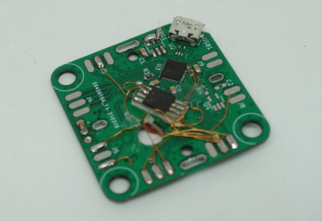
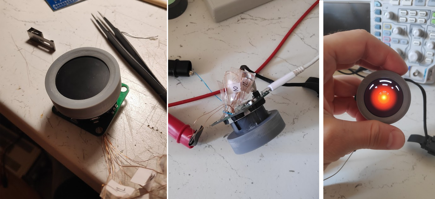
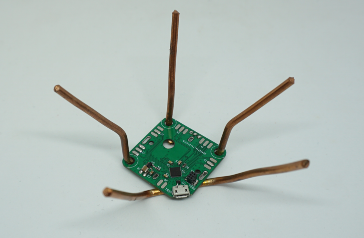
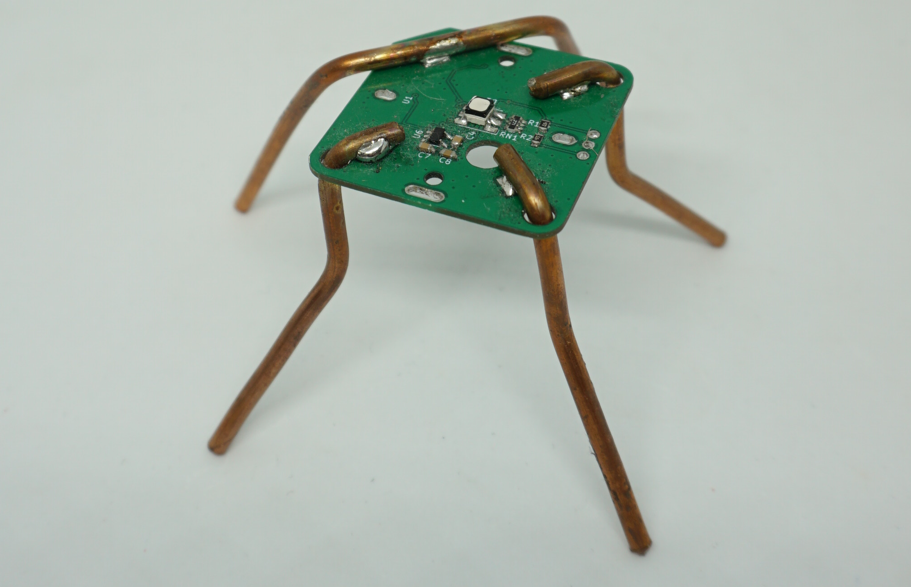
It was a rat's nest. The idea behind the hole in the board was to be able to run wires from one side to the other. At least that came in handy. I made an adaptor for the QSPI flash. I got a friend to print me some knobs. It turn out great and this gave me confidence to proceed with new design.
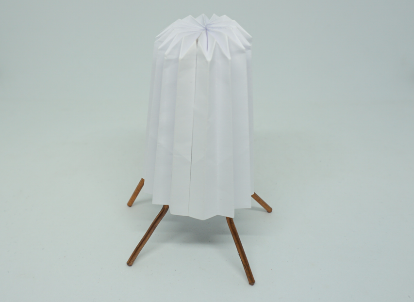
But this was not the end for this little board. It got refurbished to a bed side table lamp. Little origami skills went a long way.
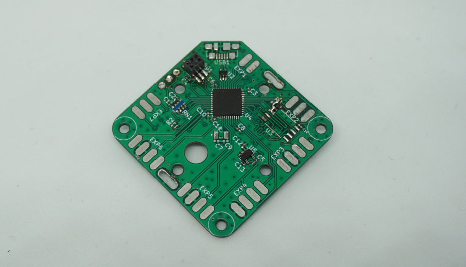
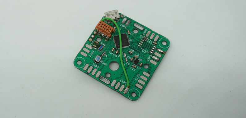
Next was a revision with STM32L422, it had more pin to accommodate the QSPI flash and the pins needed for the display. All other pins ware broken to the peripheral.
This design was almost what I need. The problem with it was a little oversight on my part about the debug port. I thought it would be a good idea to make a debug board without a cable. It became apparent how bad of an idea that was right after I connected everything.
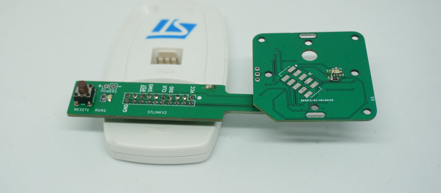
The device would tumble, get disconnected and generally a nightmare to use.
Hanse the third and last revision of the board.
Now it has a boot button, on board flash and no battery charger as it did the last one.
Hope this was fun, please leave a comment or share this page with your friends.
Cheers!
Mitko
Discussions
Become a Hackaday.io Member
Create an account to leave a comment. Already have an account? Log In.