 JT
JT-
1Dismantle the IR/Bluetooth Control Module
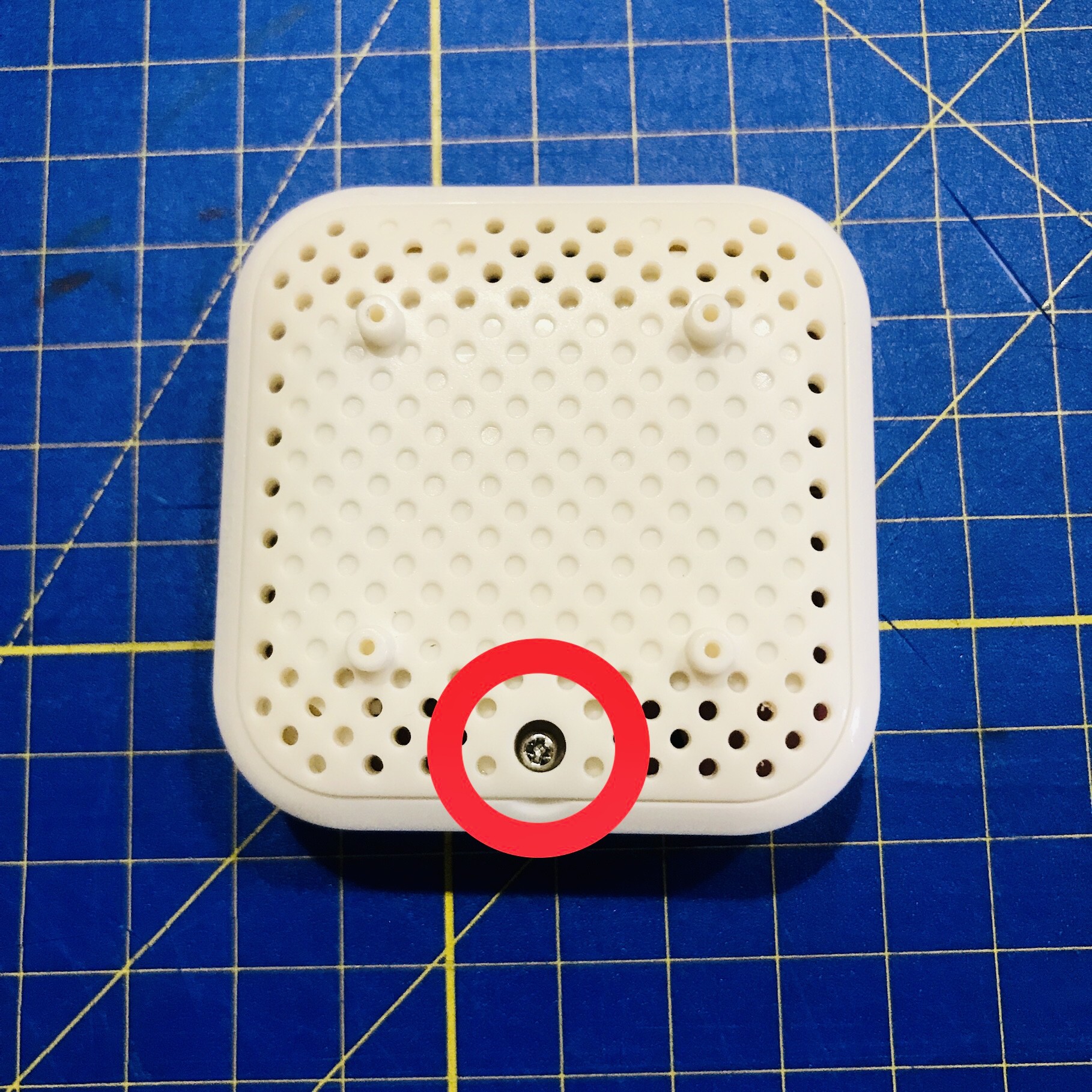
- Start by removing the screw that holds the battery cover on.
![]()
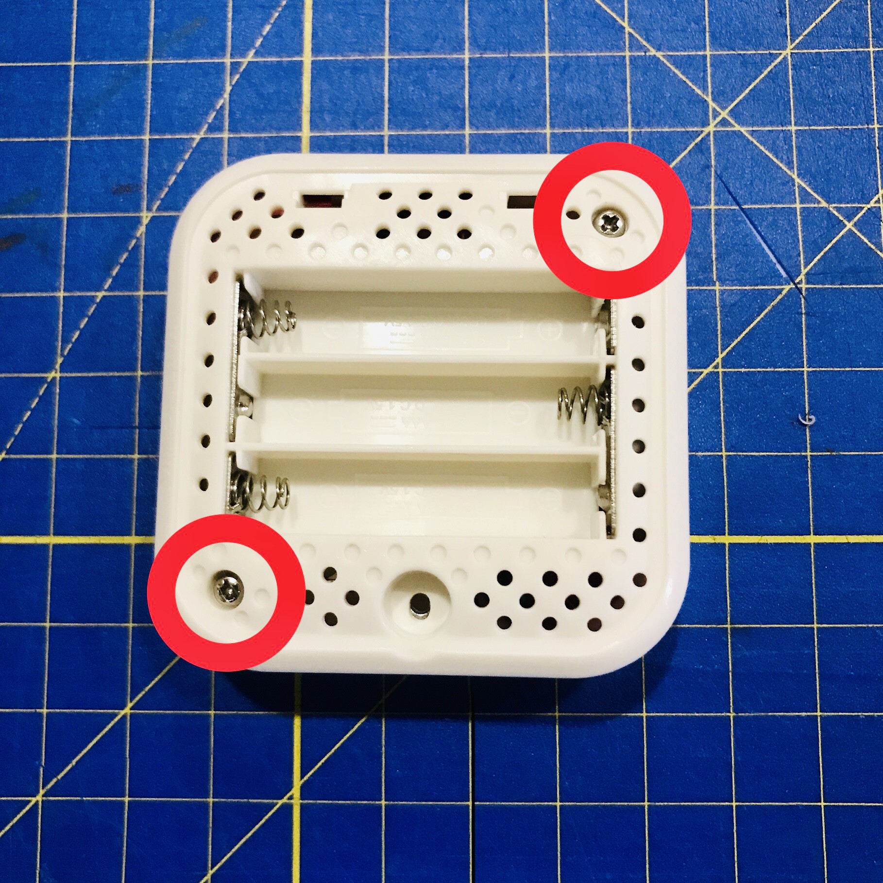
- Remove the two screws under the battery cover.
![]()
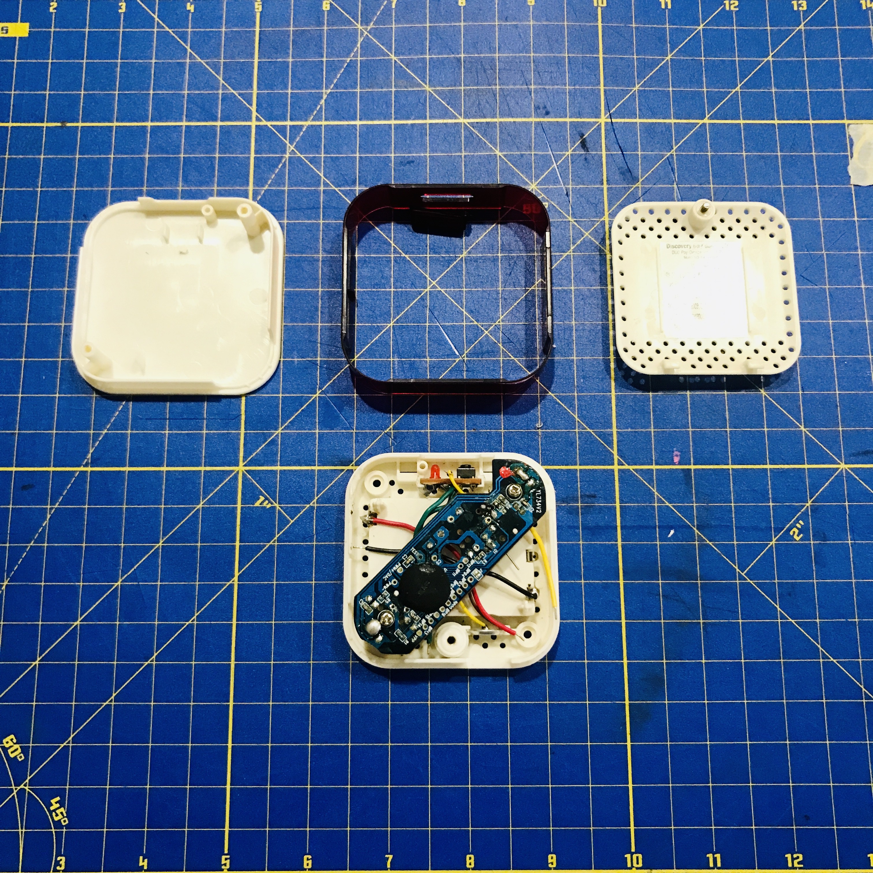
- Separate the lid, collar, and base plate from each other.
![]()
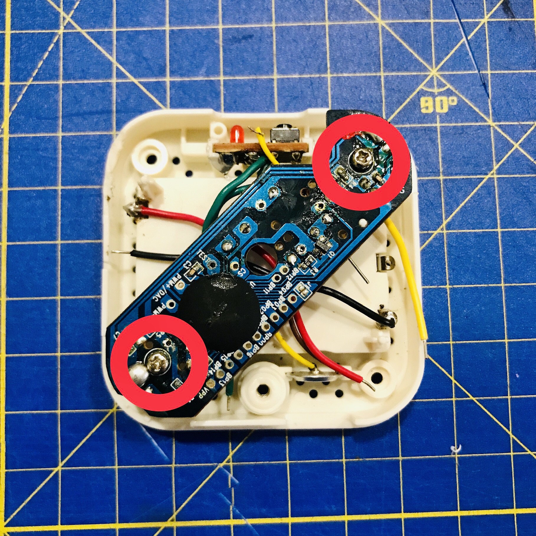
- Unscrew the control board.
![]()
- Start by removing the screw that holds the battery cover on.
-
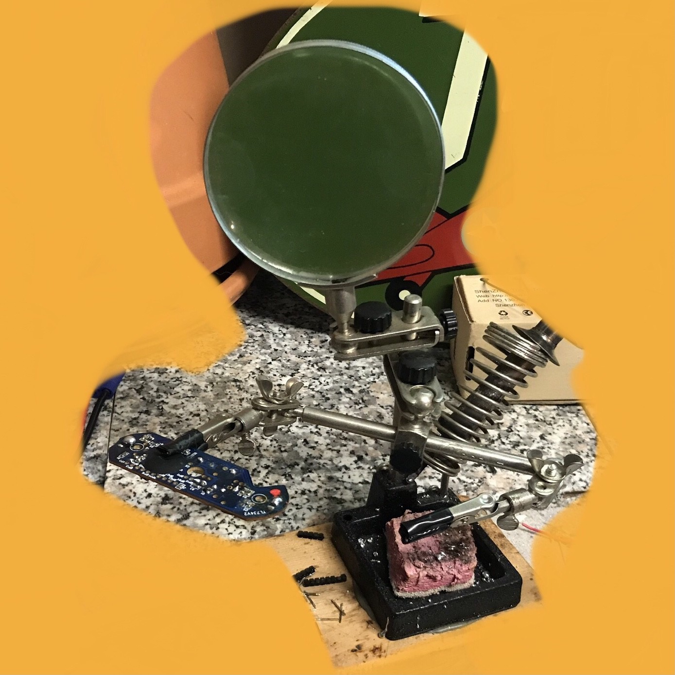
2Desolder all the wires and the two IR receivers.
- Desolder the wires from the control board or cut them close to the board and strip the ends.
- Desolder the two black IR receivers on each end of the control board. The easiest way to desolder these is to use helping-hands/third-hand soldering station (see picture below). Put a blob of fresh solder on top of the pins and give it a second to heat all three soldered pins. Then gently pull on the bottom of the IR receiver. It will be hot so gently use a pair of pliers.
![]()
-
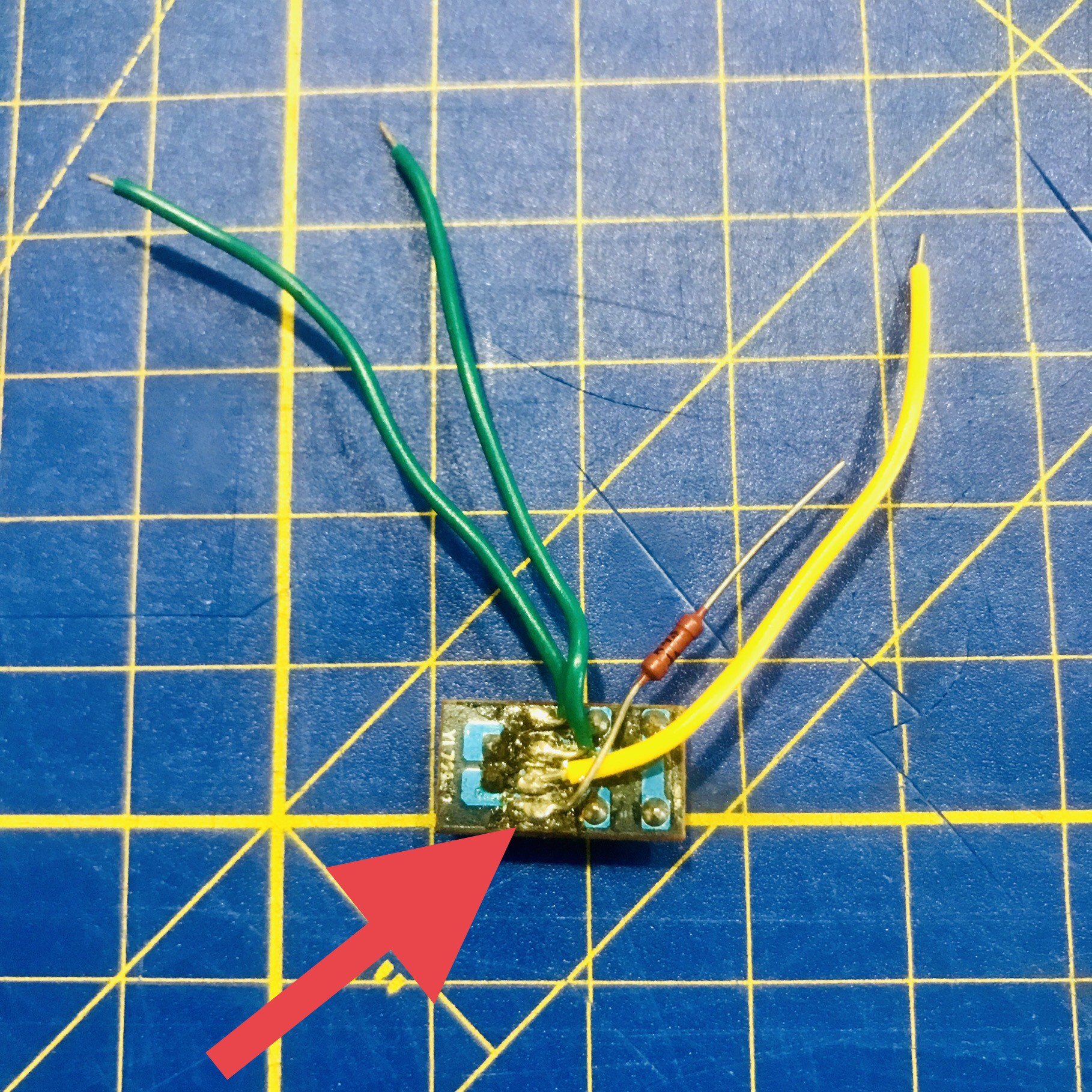
3Prepare the LED- connection
- Desolder the LED- wire off the extension board.
- Solder your 430 or 470 ohm resistor in the wire's place.
![]()
-
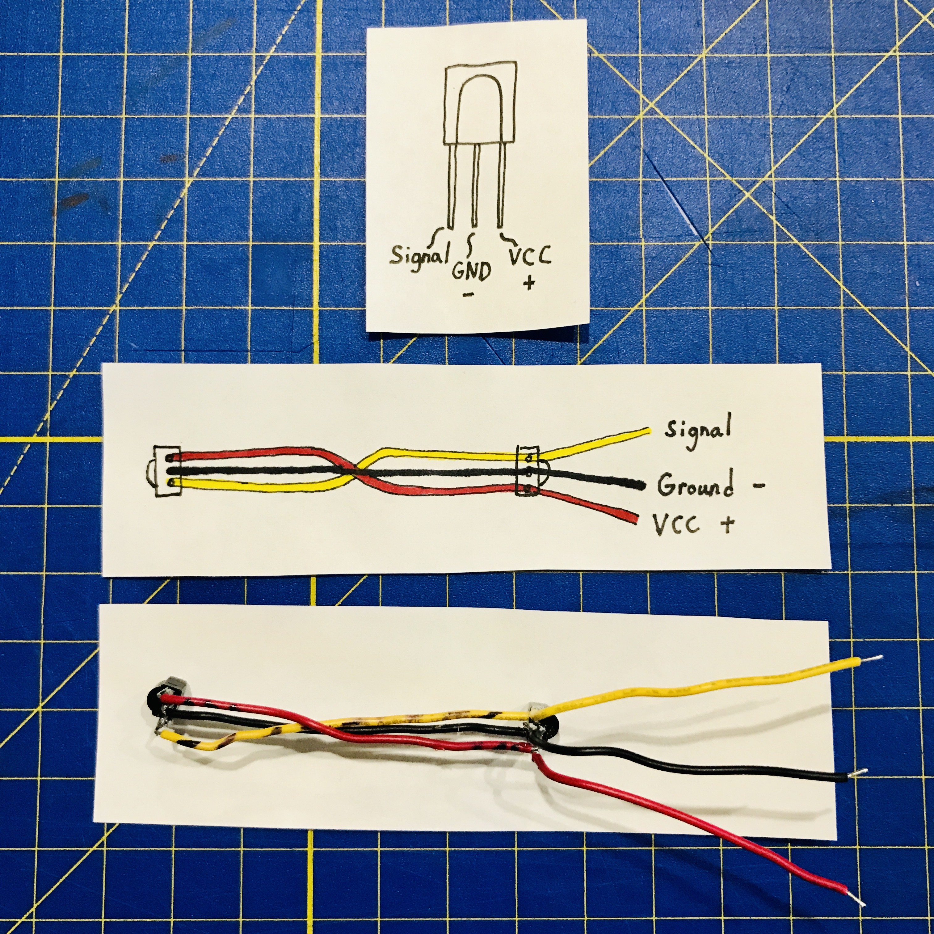
4Prepare the IR receiver connections
- Solder wires across all the IR receiver pins. The black wire is 8cm (3 1/8 inches). The yellow and red wire is 8.5cm (3 3/8 inches).
- Solder wires to the end of the assembly.
![]()
-
5Assemble the pieces
1. Assemble the pieces onto the base.
![]()
-
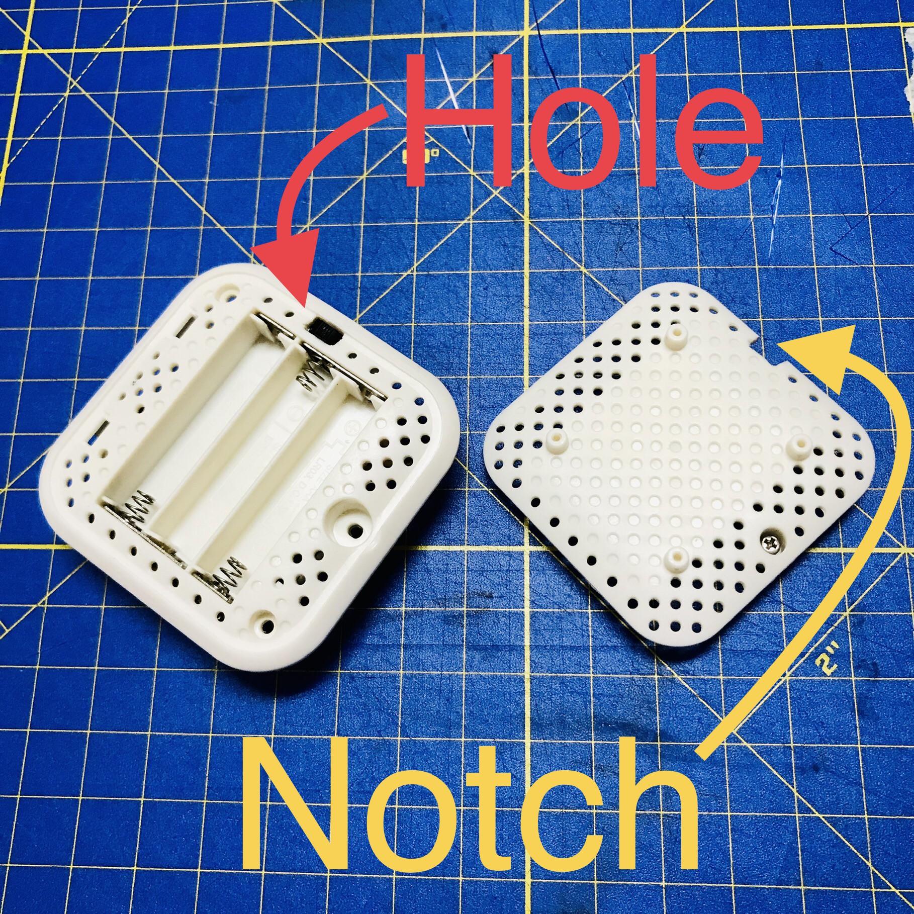
6Optional: Power Switch
If you are planning on using the AAA battery container then you will want to modify the case to fit your switch. NOTE: This is just one way of adding a switch. Please modify as needed.
1. I used a Single Pole Double Throw (SPDT) switch that I pulled out of an old RC car. It fit the gap (5.5 mm) between the battery container and the sidewall of the base. You want to start by using a tool to cut away some of the material between two holes on the base. I used a hobby knife. You could also use the hot tip of a 3D pen to melt the plastic.
2. Then you want to notch out the same area on the battery lid.
![]()
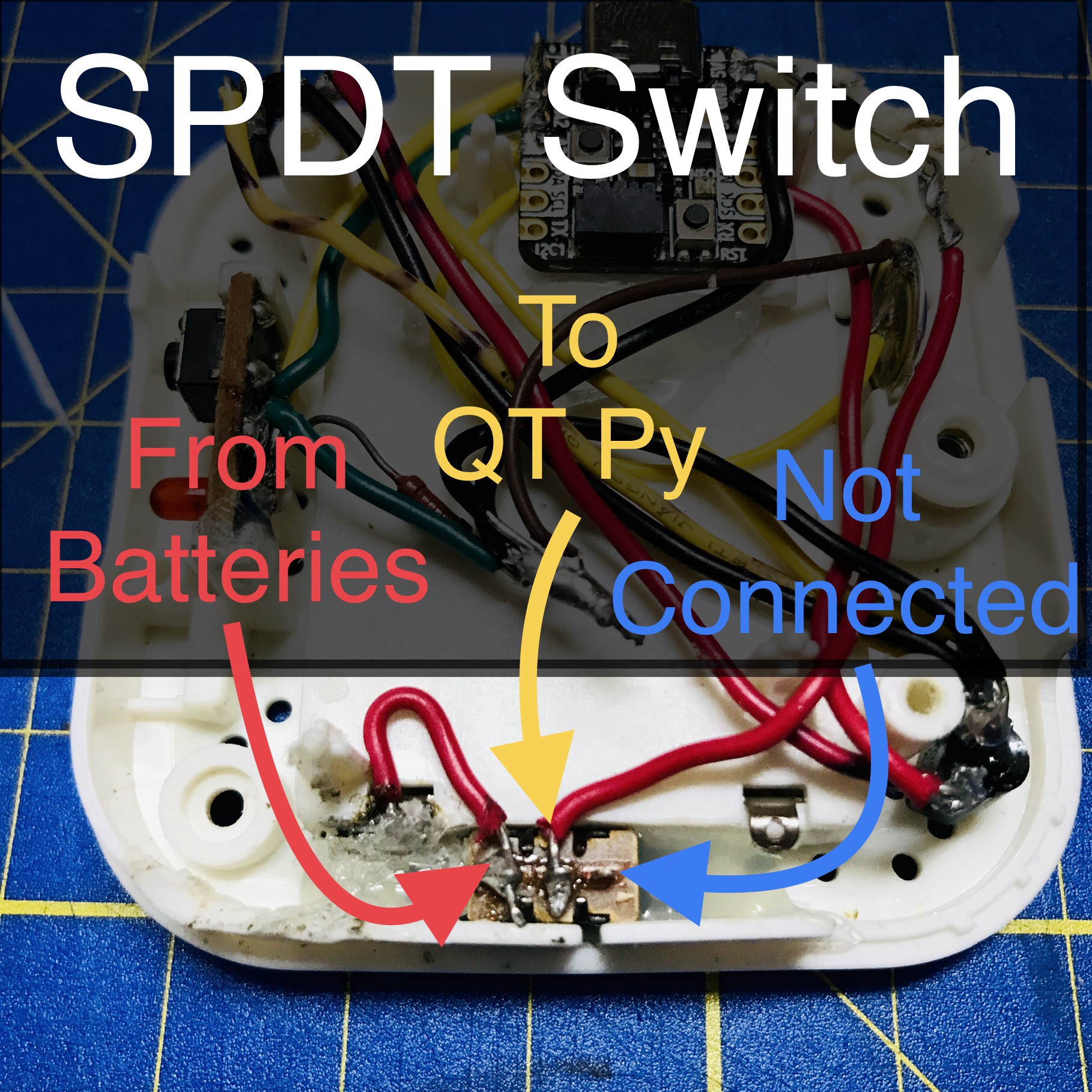
3. Solder a small wire from the battery V+ terminal to the switch and another two the center pin as shown in the photo below. NOTE: The last pin is not connected.
![]()
-
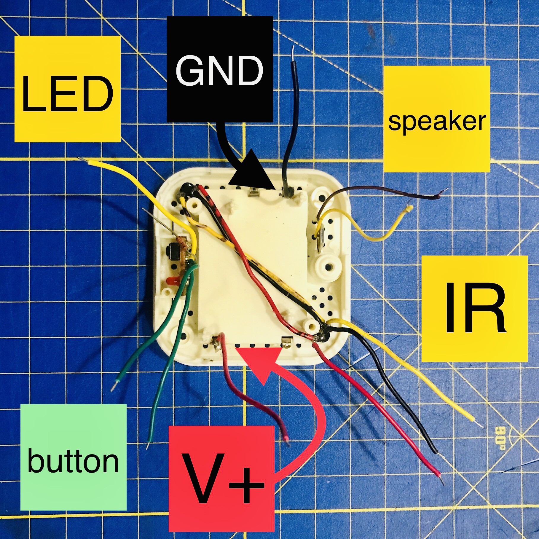
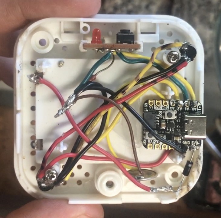
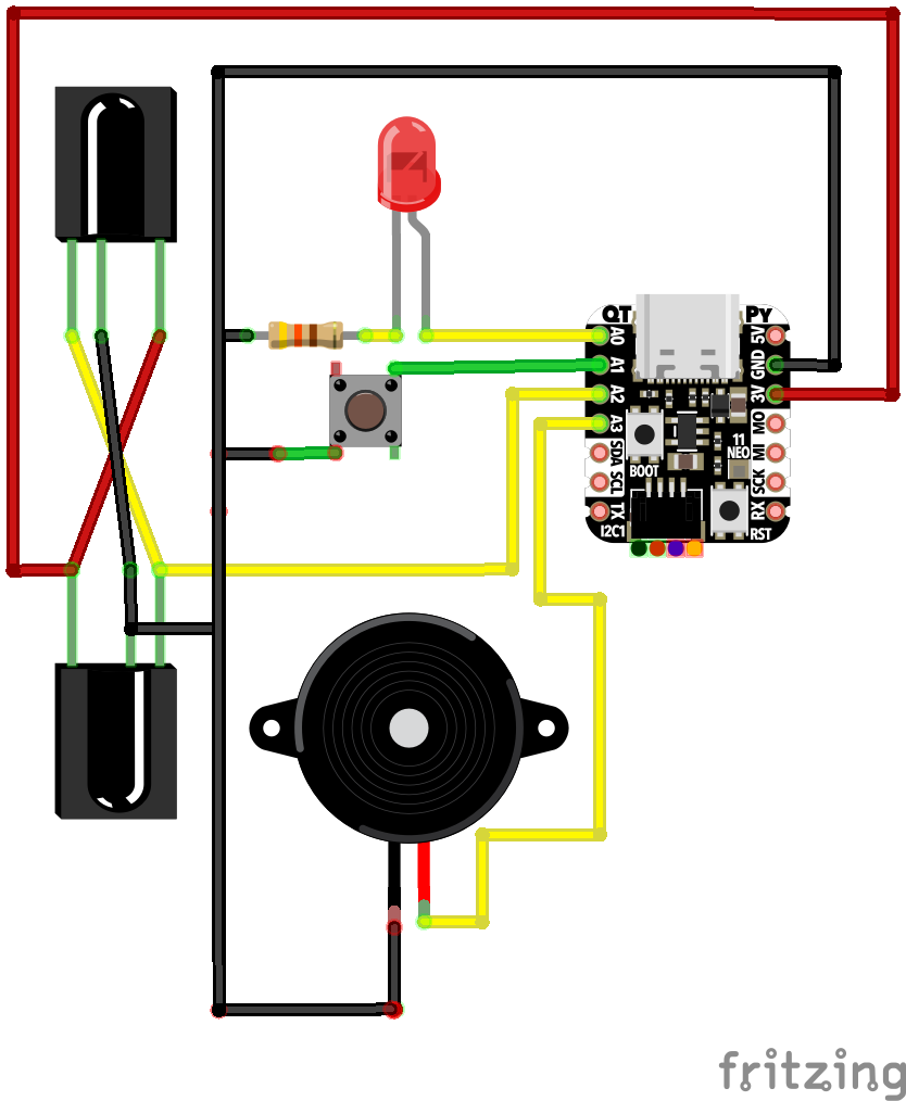
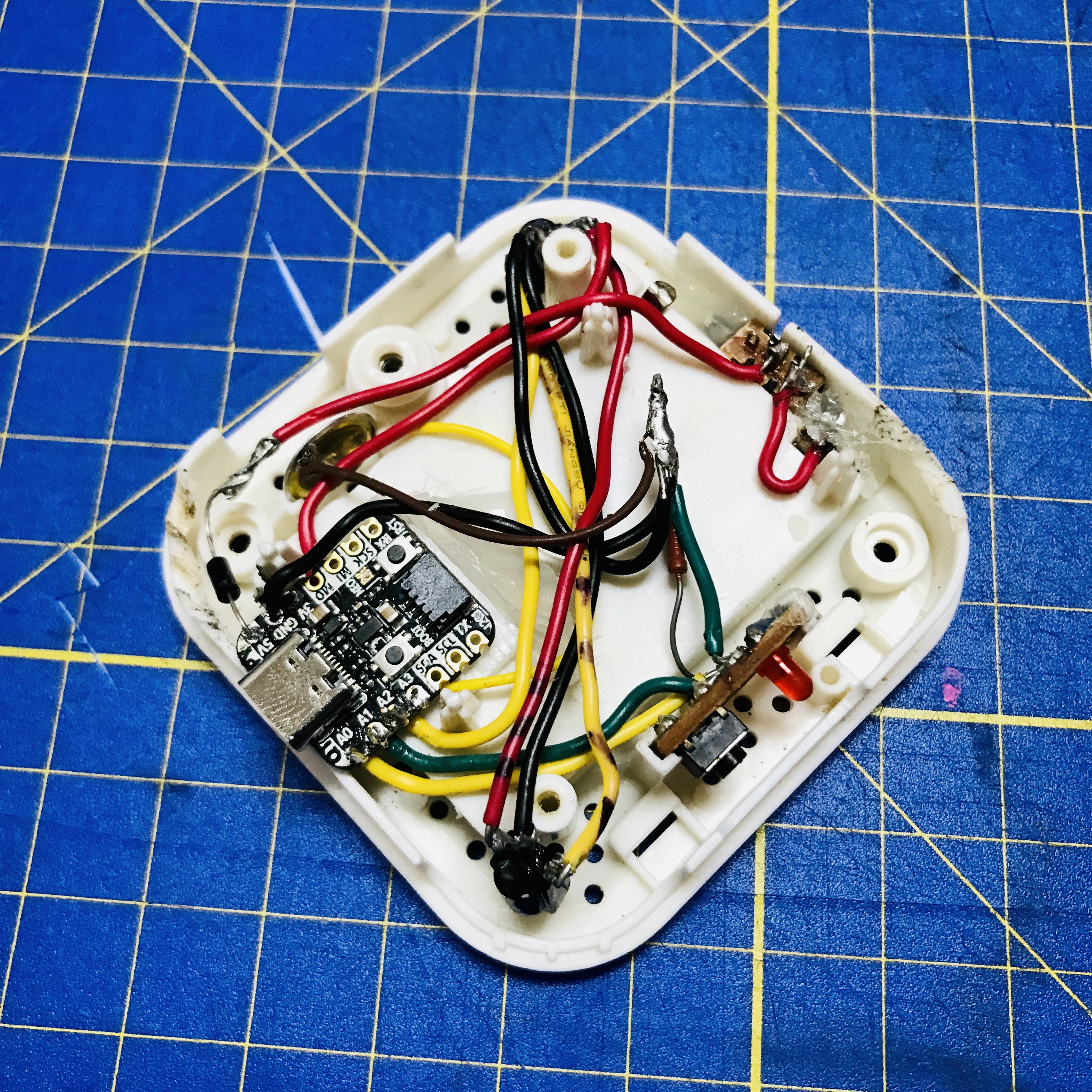
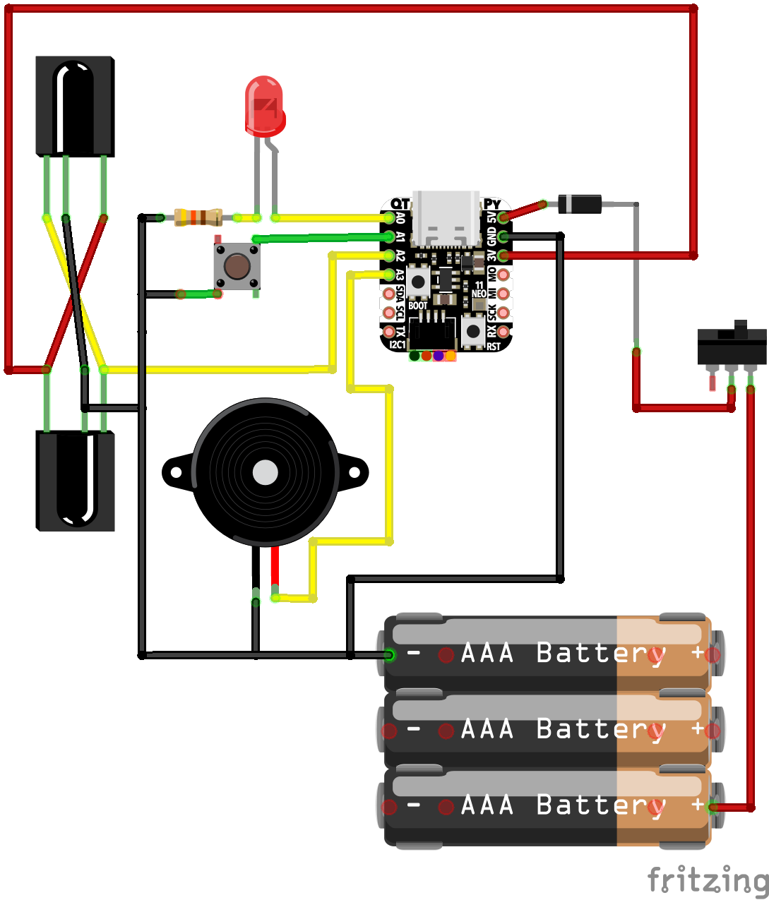
7Solder everything together
1. Use the reference picture and wiring diagrams below to solder all the pieces. Your finish product may not look like mine and that is okay. Wire it in the most convenient method. I measured each wire cut and stripped the ends and then soldered them to their desired connection point.
1.A. Reference photo and wiring diagram for powering via USB-C connection.
![]()
![]()
1.B. Reference image and wiring diagram for optional switch and diode for powering with 3 x AAA batteries or USB-C.
![]()
![]()
Reimagining Duo Pop
Breathe new life into your Duo Pop, a discontinued iOS peripheral device, with the help of Adafruit's QT Py RP2040.
Discussions
Become a Hackaday.io Member
Create an account to leave a comment. Already have an account? Log In.