 Jesús Tamez-Duque
Alice’s locomotion algorithm consists of a Finite-State Machine (FSM) that sets the desired kinematic trajectories for each motor. Once the kinematics in the form of joint angles are defined, PID speed regulators are activated controlling the motors’ speeds to move from the current position to the objective joint angles.
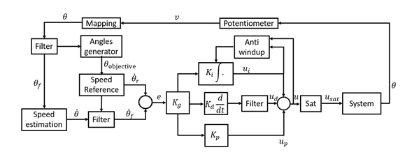
Figure 1. Block diagram of the controller, digital filters implementation and data acquisition.
The angle of the motors is indirectly obtained through potentiometers installed in the mechanical system. A mathematical mapping was constructed to convert the potentiometers’ voltage measurements to angles.
The speed is estimated through a second order approximation of the derivative. In addition, discrete third order Butterworth filters were designed and implemented for the angle and speed variables. The cutoff frequency of the filters was designed to be half the sampling frequency to avoid aliasing and still be able to recover signals within the desired spectrum, according to the Nyquist sampling rate.
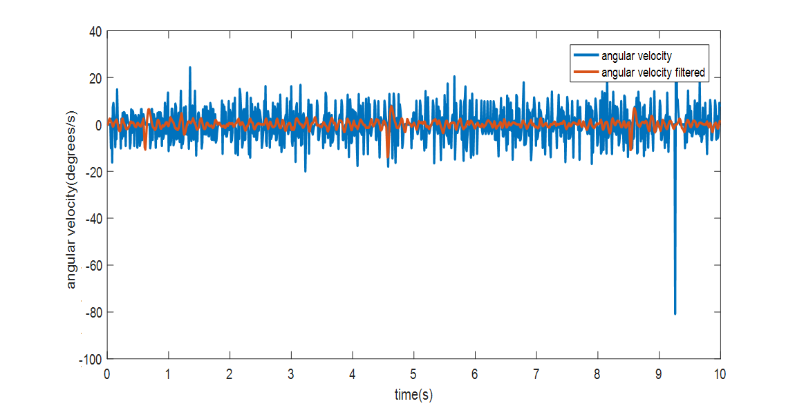
Figure 2. Angular velocity (blue) with the motor in static state, and filtered velocity (red).
To calculate manipulations, the derivative of the error was computed using a second order approximation and a Butterworth filter was applied to them using the previously mentioned cutoff frequency. Additionally, an anti-windup incremental algorithm was used to saturate the Integral action of the PID, and general non-symmetrical saturations were also implemented over the total manipulation computed by the controller. Finally, constant non-symmetrical tuned values were added to the PID’s manipulations to decrease the effect of the dead-zone nonlinearity created by the static friction of the motors.
The following graph shows the efficacy of the control algorithm in achieving target speeds while alternating joint-movement direction.
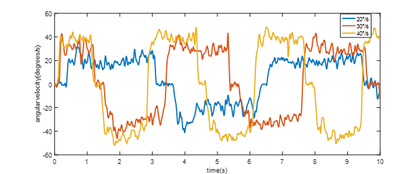
Figure 3. Performance of PID velocity controller with different target speeds and during alternating motion. For slower speeds, velocity is maintained during longer periods of time; reaching time is also longer.
Discussions
Become a Hackaday.io Member
Create an account to leave a comment. Already have an account? Log In.