 BleakyTex
This is a simple project to capture oversampled ADC data and send it to PC as audio data via USB. I made this project because I needed a convenient way to capture and process a DC - 10kHz signal, and I just used the microphone to test how it would sound like. I did not find any tutorials on sending audio data to PC, there were only basic "USB speaker" projects that relied on the STM32CubeMX generating all descriptors, handlers etc and didn't really explain how to modify the program for other needs.
So here I'll try to explain how to implement USB microphone class on STM32F407 MCU using the STM USB Audio class library. This tutorial should work even for STM32F0 family, so don't worry if you don't have the board that I've used. Initially I wanted to make this on a blue pill board but the chip shortage didn't let me to.
This tutorial assumes that you're familiar with basic architecture of the USB protocol, like descriptors, host requests and packet structure.
0. Schematics
To communicate with MAX9814 microphone amplifier, we're going to need an ADC input to sample the audio and a GPIO output to set the gain.
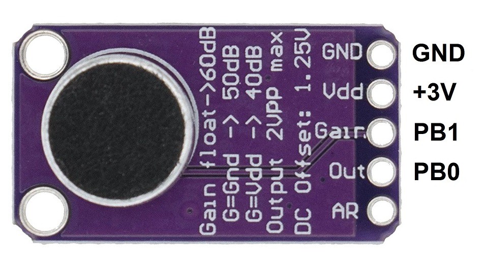
I've allocated the PB0 as ADC input and PB1 as GPIO pin, and set it to LOW to set the gain to 50 dB because I found it the most optimal. You can also just connect the Gain pin to GND for the same result.
1. Project setup
Launch STM32CubeMX and configure the project. I've attached the .ioc file to this project, so if anything is not clear, you can check anything you want yourself.
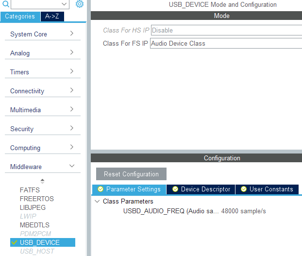
Enable USB_OTG_FS peripheral and add the Audio Device Class library to the project in the Middleware/USB_DEVICE. You can specify the sampling frequency there and a different VID/PID if you already used default ones in your other projects.
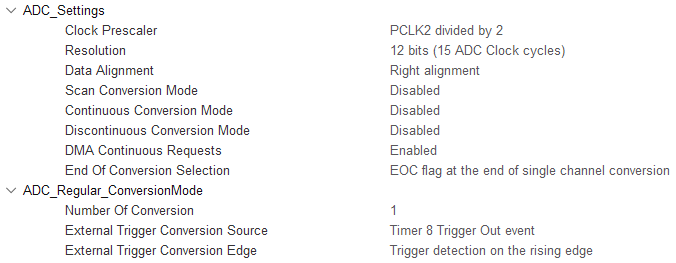
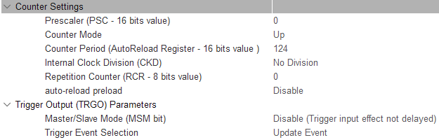
Next, let's configure the ADC. We will use a timer TIM8 as an ADC conversion trigger to get the precise sampling timing:
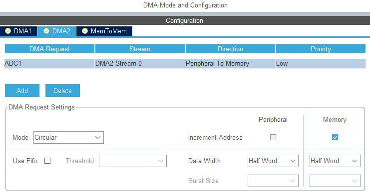
We're going to use DMA to sample the ADC because it reduces the CPU load and in my opinion it's easier to work with. Notice that circular mode is used; in normal mode I was getting weird distorted sound, apparently due to timing issues.
Now let's set up the timer. I've decided to oversample for 2 additional bits to achieve 14 bits resolution. For this, we're going to need 2^(2*2) = 16 times higher sampling frequency. I want 48 kHz output sampling frequency, so ADC sampling frequency has to be 48*16 = 768 kHz. I've set the APB2 frequency to 96 MHz, so to get the 768 kHz from that, we need to set the timer period to 96/0.768 - 1 = 124:
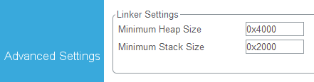
Finally, in the Project Manager tab we should increase the heap size, because to allocate the USB data structure, USB library needs more heap space than available by default.
Setup is complete, you may generate the code, compile, flash it and connect the MCU to PC. It should appear as a speaker and we'll turn it into the microphone shortly.
2. The USB descriptor
The USB descriptor generated by STM32CubeMX makes the MCU appear as a speaker. We're going to edit it to appear as a 1 channel, 16 bit / 48 kHz microphone. Open the usbd_audio.c file and locate the USBD_AUDIO_CfgDesc array. The audio device descriptor structure is shown below, and we will look closely into some of its parts:
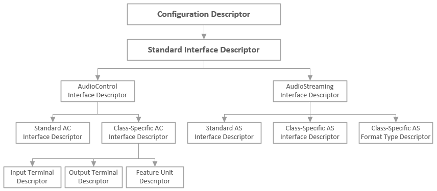
Configuration descriptor and Standard Interface descriptor are left unchanged, and we'll get to the class-specific AC interface descriptor later.
2.1. Input Terminal Descriptor
Input terminals are used to record sounds, but since the descriptor was initially made for the speaker, it's set up as a regular USB streaming terminal. To turn it into the microphone terminal, we should change the wTerminalType field to 0x0201. Full list of input and output terminal types is provided in the USB Device Class Definition for Terminal Types document.
Now we should configure the audio channels. We want one mono channel. To set this up, we should set the bNrChannels field to 0x01...
Read more »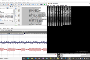
 zpekic
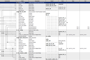
 Bruce Land
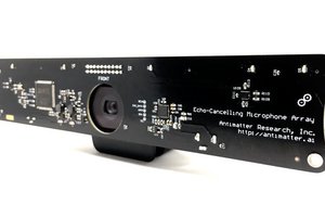
 Jim
Jim
 Paul Stoffregen