 BleakyTex
This is a simple project to capture oversampled ADC data and send it to PC as audio data via USB. I made this project because I needed a convenient way to capture and process a DC - 10kHz signal, and I just used the microphone to test how it would sound like. I did not find any tutorials on sending audio data to PC, there were only basic "USB speaker" projects that relied on the STM32CubeMX generating all descriptors, handlers etc and didn't really explain how to modify the program for other needs.
So here I'll try to explain how to implement USB microphone class on STM32F407 MCU using the STM USB Audio class library. This tutorial should work even for STM32F0 family, so don't worry if you don't have the board that I've used. Initially I wanted to make this on a blue pill board but the chip shortage didn't let me to.
This tutorial assumes that you're familiar with basic architecture of the USB protocol, like descriptors, host requests and packet structure.
0. Schematics
To communicate with MAX9814 microphone amplifier, we're going to need an ADC input to sample the audio and a GPIO output to set the gain.
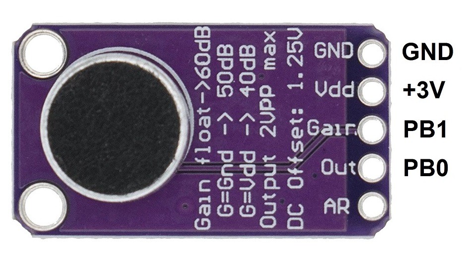
I've allocated the PB0 as ADC input and PB1 as GPIO pin, and set it to LOW to set the gain to 50 dB because I found it the most optimal. You can also just connect the Gain pin to GND for the same result.
1. Project setup
Launch STM32CubeMX and configure the project. I've attached the .ioc file to this project, so if anything is not clear, you can check anything you want yourself.
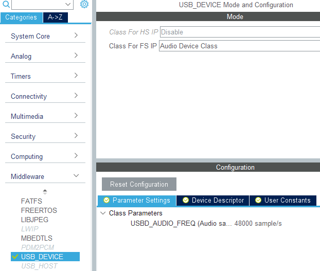
Enable USB_OTG_FS peripheral and add the Audio Device Class library to the project in the Middleware/USB_DEVICE. You can specify the sampling frequency there and a different VID/PID if you already used default ones in your other projects.
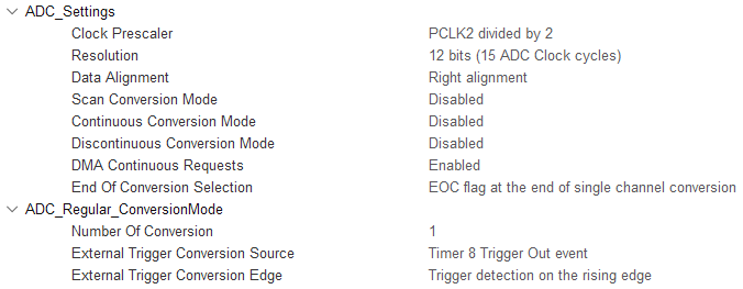
Next, let's configure the ADC. We will use a timer TIM8 as an ADC conversion trigger to get the precise sampling timing:
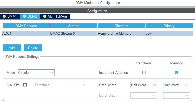
We're going to use DMA to sample the ADC because it reduces the CPU load and in my opinion it's easier to work with. Notice that circular mode is used; in normal mode I was getting weird distorted sound, apparently due to timing issues.
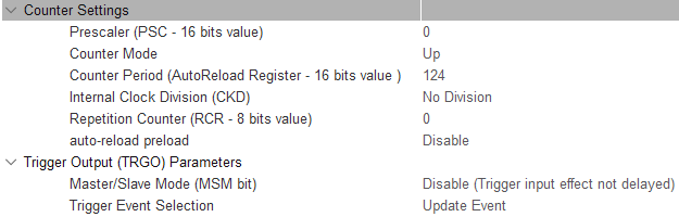
Now let's set up the timer. I've decided to oversample for 2 additional bits to achieve 14 bits resolution. For this, we're going to need 2^(2*2) = 16 times higher sampling frequency. I want 48 kHz output sampling frequency, so ADC sampling frequency has to be 48*16 = 768 kHz. I've set the APB2 frequency to 96 MHz, so to get the 768 kHz from that, we need to set the timer period to 96/0.768 - 1 = 124:
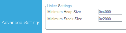
Finally, in the Project Manager tab we should increase the heap size, because to allocate the USB data structure, USB library needs more heap space than available by default.
Setup is complete, you may generate the code, compile, flash it and connect the MCU to PC. It should appear as a speaker and we'll turn it into the microphone shortly.
2. The USB descriptor
The USB descriptor generated by STM32CubeMX makes the MCU appear as a speaker. We're going to edit it to appear as a 1 channel, 16 bit / 48 kHz microphone. Open the usbd_audio.c file and locate the USBD_AUDIO_CfgDesc array. The audio device descriptor structure is shown below, and we will look closely into some of its parts:
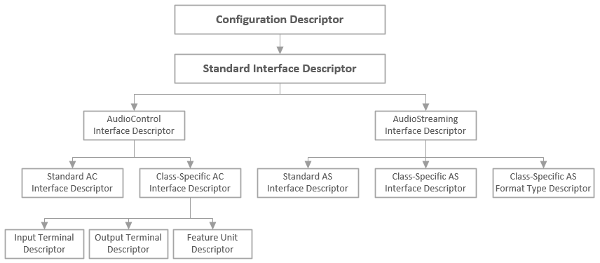
Configuration descriptor and Standard Interface descriptor are left unchanged, and we'll get to the class-specific AC interface descriptor later.
2.1. Input Terminal Descriptor
Input terminals are used to record sounds, but since the descriptor was initially made for the speaker, it's set up as a regular USB streaming terminal. To turn it into the microphone terminal, we should change the wTerminalType field to 0x0201. Full list of input and output terminal types is provided in the USB Device Class Definition for Terminal Types document.
Now we should configure the audio channels. We want one mono channel. To set this up, we should set the bNrChannels field to 0x01 (because 1 channel) and wChannelConfig to 0x0000, which corresponds to Mono channel configuration. Full list of possible channel configurations (along with the structure of various audio descriptors) is provided in the USB Device Class Definition for Audio Devices document.
After modification the descriptor should look like this:
/* Mic Input Terminal Descriptor */
AUDIO_INPUT_TERMINAL_DESC_SIZE,     /* bLength */
AUDIO_INTERFACE_DESCRIPTOR_TYPE,    /* bDescriptorType */
AUDIO_CONTROL_INPUT_TERMINAL,       /* bDescriptorSubtype */
0x01,                               /* bTerminalID */
0x01,                               /* wTerminalType = 0x0201 = Microphone */
0x02,
0x00,                               /* bAssocTerminal - No Associated Terminal */
0x01,                               /* bNrChannels = 1 */
0x00,                               /* wChannelConfig = 0x0000 = Mono */
0x00,
0x00,                               /* iChannelNames */
0x00,                               /* iTerminal */
Next goes the Feature Unit descriptor, but we don't need it, so it can be removed.
2.2. Output Terminal Descriptor
Output terminals are used to produce sounds, and in case of a microphone, we won't be producing any sounds, so wTerminalType field should be changed to 0x0101 — USB streaming terminal. Also since we removed the feature unit descriptor, bTerminalID field should be changed to 0x02 (because now it's a second terminal in the list) and the bSourceID should be changed to 0x01, because the previous (input) terminal has bTerminalID = 0x01.
After modification the descriptor should look like this:
/* Mic Output Terminal Descriptor */
0x09,                                /* bLength */
AUDIO_INTERFACE_DESCRIPTOR_TYPE,     /* bDescriptorType */
AUDIO_CONTROL_OUTPUT_TERMINAL,       /* bDescriptorSubtype */
0x02,                                /* bTerminalID */
0x01,                                /* wTerminalType = 0x0101 = USB_STREAMING */
0x01,
0x00,                                /* bAssocTerminal */
0x01,                                /* bSourceID */
0x00,                                /* iTerminal */
2.3. Interface Descriptors
Standard AS Interface descriptors are left as is, and in the Audio Streaming Interface descriptor you should only change the bTerminalLink field to 0x02 — it should the bTerminalID of the terminal of USB streaming type.
In the Type I Format Interface descriptor the bNrChannels field should be changed to 0x01, because we're going to have only 1 channel.
2.4. Endpoint Descriptors
These describe the data direction format that will be sent over the USB bus. So in the Standard Endpoint descriptor we need to change the data transfer direction in the bEndpointAddress field (we'll use the AUDIO_IN_EP macro for this) and we'll change the wMaxPacketSize field to the MIC_PACKET_SZE macro.
After modification the descriptor should look like this:
/* Endpoint 1 - Standard Descriptor */
AUDIO_STANDARD_ENDPOINT_DESC_SIZE,    /* bLength 0x09 */
USB_DESC_TYPE_ENDPOINT,               /* bDescriptorType 0x05 */
AUDIO_IN_EP,                          /* bEndpointAddress: IN endpoint 1 */
USBD_EP_TYPE_ISOC,                    /* bmAttributes */
MIC_PACKET_SZE(USBD_AUDIO_FREQ),      /* wMaxPacketSize in Bytes (Freq(kHz)*1(Channels)*2(16bit=2bytes))*/
AUDIO_FS_BINTERVAL,                   /* bInterval 0x01 */
0x00,                                 /* bRefresh */
0x00,                                 /* bSynchAddress */
The Audio Streaming descriptor is left as is.
Now the macros. Add AUDIO_IN_EP and MIC_PACKET_SZE to the usbd_audio.h file:
#define AUDIO_IN_EP            0x81U
#define MIC_PACKET_SZE(frq)    (uint8_t)(((frq * 1U * 2U)/1000U) & 0xFFU), \
                               (uint8_t)((((frq * 1U * 2U)/1000U) >> 8) & 0xFFU)
AUDIO_IN_EP is endpoint #1, having the IN direction. 0x81 is equal to 10000001 in binary, and the MSB here is set to 1, indicating the IN direction of the endpoint. First 4 bits contain the number of the endpoint, which is 1.
MIC_PACKET_SZE defines the packet size, derived from the sample frequency, number of channels and the bit depth. It also splits the result into two 8-bit values since the descriptor bit fields are 8-bit (so is the array, containing the descriptor). USB FS sends packet at the 1 kHz rate, and we should specify how much audio data should be sent in one such transfer. This yields us the formula to calculate this value:
wMaxPacketSize = (fs * Ch * N) / 1000 Hz ,
where fs — sampling frequency in Hz, Ch — number of audio channels, N — bit depth in bytes.
2.5. Descriptor size
The descriptor is almost done, the only thing left is to specify its size. First of all, in the Class-specific AC Interface Descriptor we should change the wTotalLength field to 30 (or 0x1E), since we removed the Feature Unit descriptor, and now the total size of the Class-specific AC Interface Descriptor and two Terminal descriptors is 30 bytes, not 39.
Also in the usbd_audio.h file you should change the value of the USB_AUDIO_CONFIG_DESC_SIZ macro to 100. Initially its value is 109, which is equal to the total initial descriptor size and again, since we removed the
9-byte Feature Unit descriptor, we should subtract 9.
This concludes the descriptor setup, you can try flashing the MCU and you should see the microphone in the audio devices list:
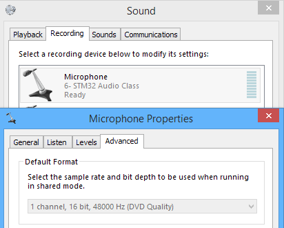
Working with descriptors may be a bit overwhelming for the beginners due to their size, and it still is for me, so double check everything. You can use Thesycon's USB descriptor dumper to check for the issues with the descriptor if you're having any.
3. Making USB transfers
We got the descriptor but we still need means to transfer the data over USB.
3.1. Add microphone data to the USB data structure
STM32CubeMX has generated a structure, which keeps the audio data for playback. It's convenient to add the microphone data variables to it and use it with provided functions. The structure can be found in usbd_audio.h and called USBD_AUDIO_HandleTypeDef. For the microphone data, we'll need a buffer and a flag variable to point at the beginning or the middle of the buffer, depending on which half of it is being transferred or filled by ADC.
But first we need to determine the size of a buffer. After some trial and error, I figured that a single packet buffer size works best:
#define AUDIO_IN_PACKET (uint16_t)(((USBD_AUDIO_FREQ * 2U) / 1000U))
Now let's add the forementioned two variables into the structure:
typedef struct
{
  uint32_t alt_setting;
  /* speaker data */
  uint8_t buffer[AUDIO_TOTAL_BUF_SIZE];
  AUDIO_OffsetTypeDef offset;
  uint8_t  rd_enable;
  uint16_t rd_ptr;
  uint16_t wr_ptr;
  /* mic data */
  int16_t in_buffer[AUDIO_IN_PACKET]; // add this
  uint8_t in_buffer_half;             // and this
  /* control data */
  USBD_AUDIO_ControlTypeDef control;
} USBD_AUDIO_HandleTypeDef;
3.2. Initialize the endpoint
Before we send any actual data, the USB data structure and the endpoint must be initialized. This happens in the USBD_AUDIO_Init() function, located in usbd_audio.c. Right now it contains the initialization for the speaker but since we don't need the speaker functionality, we can remove it. Here's he completed function:
static uint8_t USBD_AUDIO_Init(USBD_HandleTypeDef *pdev, uint8_t cfgidx)
{
  USBD_AUDIO_HandleTypeDef *haudio;

    /* Allocate Audio structure */
  haudio = USBD_malloc(sizeof(USBD_AUDIO_HandleTypeDef));
  pdev->pClassData = (void *)haudio;

    /* Open IN endpoint (mic) */
  USBD_LL_OpenEP (pdev, AUDIO_IN_EP, USBD_EP_TYPE_ISOC, AUDIO_IN_PACKET);
  pdev->ep_in[AUDIO_IN_EP & 0xFU].is_used = 1U;

    /* Make a dummy transfer */
  USBD_LL_FlushEP  (pdev, AUDIO_IN_EP);
  USBD_LL_Transmit (pdev, AUDIO_IN_EP,
                   (uint8_t*)&haudio->in_buffer[AUDIO_IN_PACKET * !!haudio->in_buffer_half], AUDIO_IN_PACKET);

  return (uint8_t)USBD_OK;
}
It took me quite a while to figure that a dummy transmission has to be made for the regular transfers to start working and that you need to flush the endpoint before making transmissions. If you don't make this transfer, you will get no audio from the mic, because the host will not request any data from it.
3.3. Implement USB data transfer
Now's the time to make a data IN request handler, which will send the data to the host when it asks for it. There's a stub for this function - USBD_AUDIO_DataIn(), we just need to add code into it:
static uint8_t USBD_AUDIO_DataIn(USBD_HandleTypeDef *pdev, uint8_t epnum)
{
  USBD_AUDIO_HandleTypeDef *haudio;
  uint8_t retval = USBD_OK;

  haudio = (USBD_AUDIO_HandleTypeDef*) pdev->pClassData;

  if (epnum == (AUDIO_IN_EP & 0x7F))
  {
     haudio->in_buffer_half = !haudio->in_buffer_half;    // also serves as init to 1 or 0
     uint16_t prev = (AUDIO_IN_PACKET / 2) * !haudio->in_buffer_half;
     ADC_to_MIC();

     USBD_LL_FlushEP  (pdev, AUDIO_IN_EP);
     USBD_LL_Transmit (pdev, AUDIO_IN_EP, (uint8_t*)(haudio->in_buffer + prev), AUDIO_IN_PACKET);
  }

  return (uint8_t)USBD_OK;
}
If data from AUDIO_IN_EP is requested, first we invert the buffer pointer in_buffer_half twice to initialize it to 1 or 0 and get rid of the possible malloc artifacts in this variable (remember that malloc function is used to allocate the USB data structure).
Then we get the first or the middle buffer index into the variable prev (which shows, which half of the buffer was filled by ADC in the previous cycle) and start the ADC conversion. While it's busy filling the other half of the buffer, we send the data to the host. And don't forget to flush the endpoint before making transfers.
The last thing we need to do is to add a prototype for the ADC_to_MIC() function and include the main.h file to access this function:
#include "main.h"
void ADC_to_MIC(void);
4. Sample the audio
This is the last part. We're going to set up the ADC to oversample the signal and send it to the USB buffer.
First we need a buffer to keep the raw ADC data for further oversampling. The ADC buffer has to keep only half of the USB buffer, that multiplied by 16 since we're oversampling by 2 bits:
#define OSA_BUF_SIZE 16
int16_t adc_buffer[OSA_BUF_SIZE * AUDIO_IN_PACKET / 2] = {0};
Also we need to specify the USB data structure to access it from main.c:
extern USBD_HandleTypeDef hUsbDeviceFS;
The ADC conversion function is simple — just start the DMA transfer:
void ADC_to_MIC(void)
{
   HAL_ADC_Start_DMA(&hadc1, (uint32_t*)adc_buffer, OSA_BUF_SIZE * (AUDIO_IN_PACKET / 2)); // Start ADC transfer into oversampling buffer
}
Most of the fun happens in the interrupt that triggers on completed conversion — when the ADC buffer is filled:
void HAL_ADC_ConvCpltCallback(ADC_HandleTypeDef* hadc) {
  USBD_AUDIO_HandleTypeDef *haudio = hUsbDeviceFS.pClassData;
  int16_t *buf_part = haudio->in_buffer + (AUDIO_IN_PACKET / 2) * haudio->in_buffer_half;  // USB mic buffer access

  /* Oversample for +2 bits */
  for (uint16_t i = 0; i < (AUDIO_IN_PACKET / 2); i++) {
  int32_t avg_value = 0;
    for (uint16_t j = 0; j < OSA_BUF_SIZE; j++) {
      avg_value += adc_buffer[OSA_BUF_SIZE * i + j];
    }
    // bit shift for signed variables is undefined behaviour
    // Don't forget the mic amp offset: 1.25V (6826 ADC value)
    buf_part[i] = (avg_value / 4) - 6826;
  }
}
Here we fill one half of the USB buffer (the one that is not being transferred right now) with oversampled ADC data. Basically we should sum up the 16 consecutive samples and shift them by 2 bits to the right, but shifting signed variables is not a good idea, so instead of bit shifting I'm just dividing by 4, which gives the same result. And also the microphone amplifier output offset should be taken into account, since it may lead to clipping at high signal levels. By subtracting the offset from the sample value, we shift the baseline down to zero and thus we can utilize the full 16 bit dynamic range.
Finally, in the main() function, TIM8 should be enabled for the ADC to start sampling:
HAL_TIM_Base_Start(&htim8);
That's it, we're done. You may flash the MCU and the microphone should work.
5. Performance
I was really surprised how good a $1 microphone from Aliexpress can sound. I couldn't come up with anything to record, so instead I measured the output noise spectrum by selecting the USB microphone as a signal source in Digilent WaveForms:
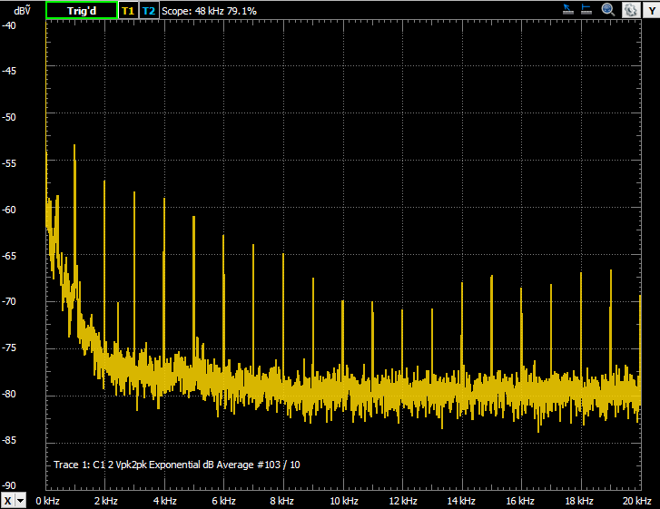
There is a barely audible 1 kHz hiss, which is probably caused by bad power supply decoupling in the STM32F4DISCOVERY board and the fact that I've used long unshielded wires to connect the microphone. My guess is that the source of the noise could be the USB transfers, which occur at exactly 1 kHz rate.