 Timescale
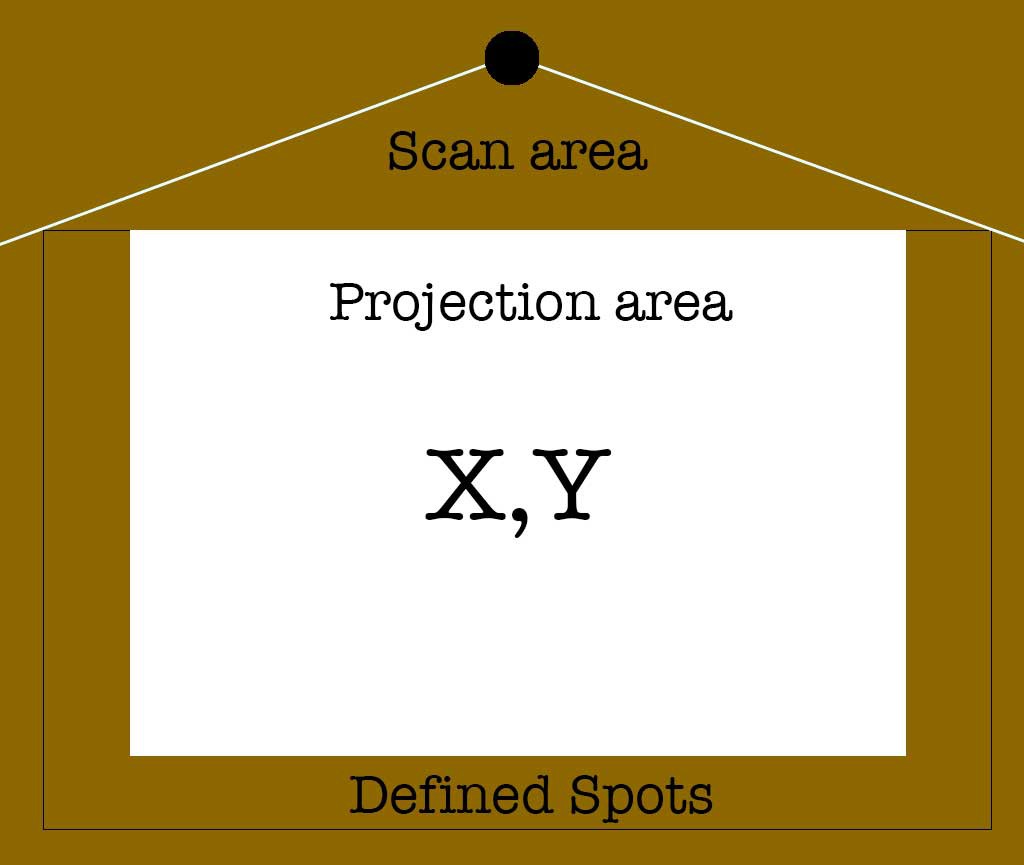
What I need is a system for interacting with a floor projection, both on and just outside of the projection area. There are ready-to-go systems that can do this to some degree. These are often fancy ceiling mounted devices with an IR camera that can track multiple users. These are also very expensive an overkill for what I need.
I need simple but reliable single user input, it's not going to be some flashy game, it's going to be an edutainment system.
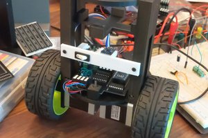
My first attempt was to build an array of ultrasonic sensors connected to a Raspberry pico. I used trimpots to dial in the distance per interaction point and the sensors were mounted on a gimbaling joint. While fun to mess around with, it because clear very quickly that this method would never work quickly and reliably, even under ideal conditions.
The range was limited, on reading errors, recovery was slow, the pico only having 3 ADC's meant that without more stuff added, I could only attach 3 pots which meant 3 sensors. But for that there would always be a solution like just using 1 pot and store the value in an eeprom module or something. No, the real problem was that at best the response time would be roughly a second. Mostly it would be 2 seconds and that is much to long for user interaction.
So after a bit of searching around, I figured this could be easily done with a 2d 360 LiDAR sensor of which there are plenty in every price range. Of course I chose the cheapest option, the venerable RPLiDAR A1. Just 100 euro's without tax and I was off to the races.
 Josh Cole
 Vignesh Ravichandran
 Naveen Sridharan
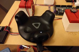
 Mike Turvey