 Anders Nielsen
Basic software features include a monitor program and IO commands to read, write and execute code.
Hardware revision 0 is missing a few features but is a complete prototype that makes it ease to write bitbanging SPI or connect a second 6522(and third) via the broken out address/data bus line of 2.54mm header - on r0 I forgot to break out the IO-select signal, so connecting multiple 6522's(or other IO) does require a bodge-wire to ~CS2.
One oddity of the build, I have to admit, is the choice of a PMS171b as a glue logic/V-sync generator. At the time I needed a working prototype and just grabbed the cheapest MCU I could find. I'm planning to replace some of the 74ls161's 4bit counters with 74hc590 8 bit counters - which should free up some board space and require fewer lines with tristate buffers (74hc245's).
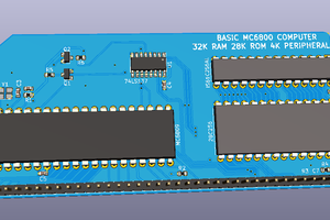
Hardware Memory Map
$0000-3FFF: ZP, Stack and RAM
$2000-27FF: Part of RAM is set aside for video RAM. Not all of it is used on screen but all is reserved. (For blanking etc)
$4000-7FFF: Input/output, etc. Onboard 6522 has address $6000.
A second, and third, and fourth 6522 can easily be added off board by using A13, A12, and A11 as CS1 and the same !CS2. The other VIA's would be addressable at $5000, $4800 and $4400.
$8000-FFFF: ROM (including reset, irq and nmi vectors at $FFFA-F)
OS Syntax
The OS isn't much for spitting out syntax errors or any help for that matter.
Current commands are:
read <16 bit address, MSB-first>
The read command enters monitor starting at the specified address.
write <start 16bit address, MSB-first> <data> [<data>..<data>]
The write command writes starting at the specified address and then enters monitor.
Exit monitor by pressing ESC
run (Jumps to the address contained in $30 and $31, LSB in $30 (!))
F1-key enters monitor without changing address.
 Gee Bartlett
 Hayden Kroepfl
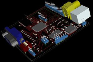
 PK
PK
 Jacob Hahn