 Sergei V. Bogdanov
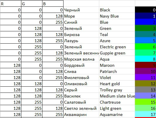
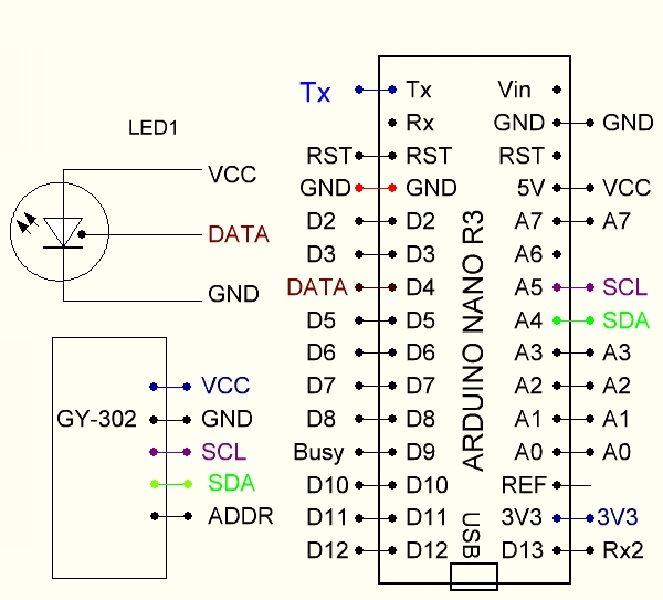
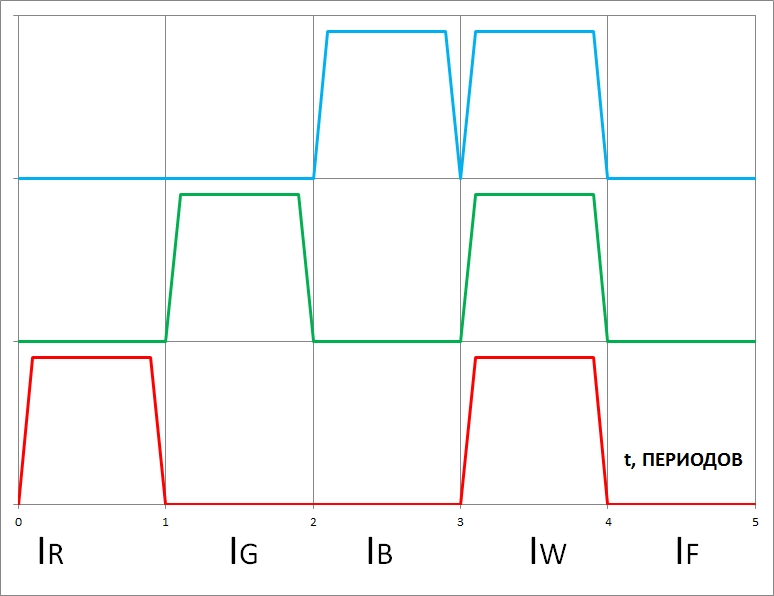
For color detection, there are specialized chips that use light filters applied to the elements of the photodiode array, but their price is very high. We offered an original solution - we took an inexpensive and widespread GY-302 module based on an integrated light sensor, and a controllable RGB (three-color - red, green, blue) LED module based on a WS2812 chip.
0%
0%
Сolor Identifier for visually impaired people
Color Identifier can identify the color of clothes (and other household), tell the color and what other colors is compartible with this one.
Become a Hackaday.io member
Already have an account? Log in.
Just one more thing
To make the experience fit your profile, pick a username and tell us what interests you.
Pick an awesome username
hackaday.io/
Your profile's URL: hackaday.io/username. Max 25 alphanumeric characters.
Pick a few interests
Projects that share your interests
People that share your interests


 Fig. 3 Slicer picture of LED-Photodilde holders.

 Alex Camilo
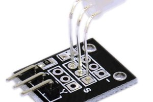
 Thomas Chanon Wangtrirat
 Jovan
Jovan