Close
0%
0%

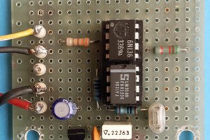
DIY ARDUINO AC DIMMER

Thanks To JLCPCB. $2 For 1-4 Layer PCBs. Get $18 Coupons: https://jlcpcb.com/RAT

Similar projects worth following
650 views
0 followers
About the Project It’s pretty simple to control the brightness of an LED, just give it a PWM signal and change the brightness. But what about a Bulb that runs on AC current? Its brightness won’t be controlled by giving it PWM signals. It will require some additional circuits and, in this article, I’ll be talking all about the AC dimming process and making. Components Required BT136 TRIAC 10KΩ Resistor MOC3021 IC Arduino Board MCT2e IC 2 Pin Terminal 47KΩ 1W Resistor Heat Sink 330Ω Resistor x2 1KΩ Resistor Working Principle In this project, I’m using the Leading-Edge Phase Dimming Method to lower down the output power. In the circuit, we have one zero-cross detector which gives the signal to the Arduino board whenever the signal crosses the zero value. A zero-cross detector is used as a reference to change the phase of the signal. By delivering the power for less than 100%, we cut down the amount of power delivered

DIY_Arduino_Dimmer_Schematics.pdf

Schematic Diagram

Adobe Portable Document Format - 94.10 kB - 09/29/2021 at 01:59

Preview

Dimmer_Gerber_albtronics.zip

Project Gerber File.

x-zip-compressed - 107.82 kB - 09/29/2021 at 01:50

Download

  • 1 × BT136 TRIAC
  • 1 × MOC3021 IC
  • 1 × MCT2e IC
  • 1 × Heat Sink
  • 2 × 2 Pin Terminal

View all 10 components

Enjoy this project?

Share

Discussions

Similar Projects

Does this project spark your interest?

Become a member to follow this project and never miss any updates