 Joao Buzzatto
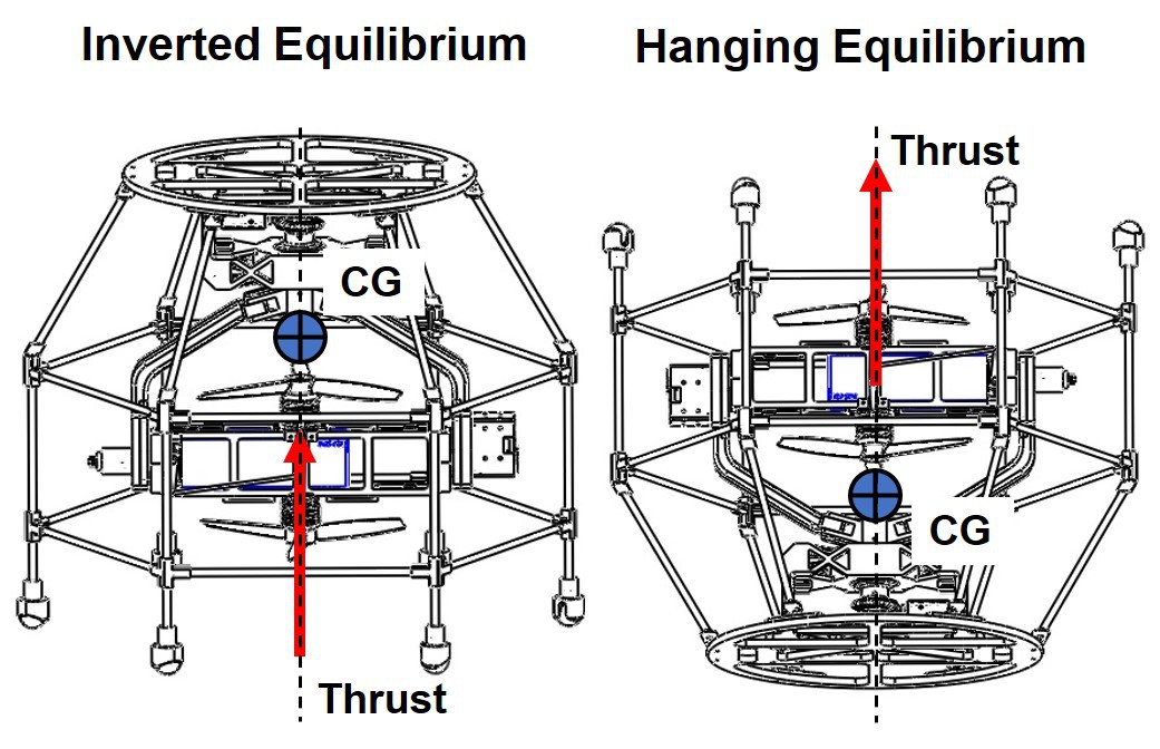
A drawback of the gimbal mechanism is its kinematic singularities points. These are points in its workspace where, when performing inverse kinematics to track a path, minimal changes on its pointing direction results in large motion of the joints. This results in the rotor-on-gimbal mechanism's inability to perform small force corrections quickly without introducing disturbances to the system when operating near such singularity points. Unfortunately, in the proposed all-terrain vehicle concept, which utilizes only one of the rotor-on-gimbal module, the Center of Gravity (CG) of the system is always aligned with the kinematic singularity for both of its stable configurations (see Fig. 1).
A possible solution to such a problem is to add control surfaces downstream to the propellers, arranged perpendicular to the second DoF. Such addition provides enough control authority in all directions even when operating at the gimbal's singularity points. However, given the limited space to fit such addition and to keep a small footprint for the rotor-on-gimbal design, it was decided to place the control surfaces between the coaxial rotors, as shown below (Fig. 2). Despite the considerable added complexity to the system, especially in the aerodynamics sense, this solution approach is lightweight, easy to incorporate, and inexpensive.
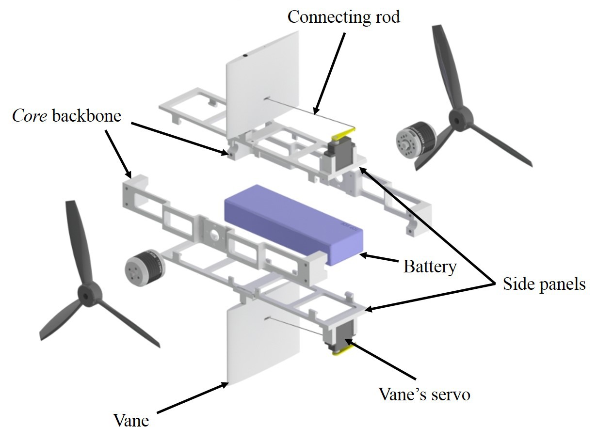
For the prototype, two 9 g HD-1900A micro servos actuate the control surfaces. They are mounted to 3D-printed PLA holders, which are glued to the battery case lids. The control surfaces, or vanes, are 3D-printed PLA NACA 0006 airfoil profiles, with 100 mm chord length and 90 mm spam. These vanes hinge about 4 mm carbon fiber rods, which are press-fitted into 3D-printed PLA holders glued to the battery case lids. The servo horns and the vanes are connected by 0.8 mm steel rods, and together they form a parallel four-bar linkage. Such parallel linkage arrangement guarantees that the motion of the control surfaces is equal to the servos' motion but translated by their separation distance.
As mentioned before, when the vehicle is at hovering its CG is aligned with the gimbal's kinematic singularity. To control the UAV in this operating point, we maintain the first DoF locked, and the vanes movement coordination performs compensations on the pitch axis. An important note here is that the control of the vanes is not based on a model. In contrast to the well-known and studied rotor typical on multirotor UAVs, at the time of writing, the authors could not find in the literature any study which describes the system used here, i. e., a counter-rotating coaxial rotor system with control surfaces placed in between them.
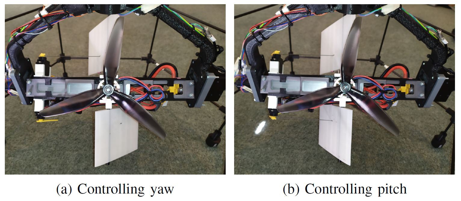
Implementation-wise, control of the vanes is done by the use of a properly set mixer on the flight controller. Given that each vane is controlled by an independent servo motor, here we consider that they can contribute to the regulation of the system in two ways: i) Help to regulate yaw, and ii) control the vehicle's pitch. To control yaw, the mixer sends commands to move the vanes deferentially with respect to the vertical direction (Fig. 3 a). To control pitch, the mixer commands the vanes to rotate symmetrically with respect to the horizontal direction (Fig. 3 b).
Discussions
Become a Hackaday.io Member
Create an account to leave a comment. Already have an account? Log In.