 Joao Buzzatto
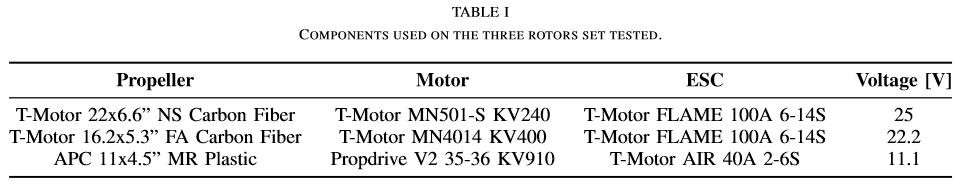
Three sets of rotors are used here. The main difference between the rotors is their KV and the recommended propeller size. Table I summarizes the components comprising the rotors sets and the testing conditions. The coaxial system experiments consist of swiping each motor's commands from 7% to 95%, divided into 10 equally spaced points, resulting in a total of 100 data points per test. With such tests, we obtain a map for the coaxial system that practically covers the whole actuation space of the rotor pair.
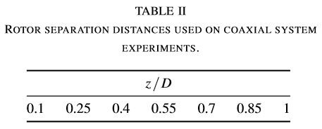
We investigate how the map characteristics (especially efficiency) changes when varying the separation distance between the rotors. Since the tests consider three different rotor sizes, the spacing between the rotors is specified as the non-dimensional ratio z/D, where z is the distance between the propellers and D is the propeller diameter. The same set of ratios is tested for the three rotor sets. The values range from 0.1 to 1 divided into 7 equally spaced points, as displayed in Table II. The range selected is considered by the authors to be a reasonable one found on most multirotor vehicles having coaxial rotors as propulsion units and being constructed of common, off-the-shelf components.
For each rotor set, testing across all separation ratios results is 700 data points in total, where each data point has individual rotor information about the command sent, thrust, torque, voltage, current, and rotation speed. Presenting all the data in this document is impossible, thus we focus on discussing the most interesting results for all rotor sets across all distances.
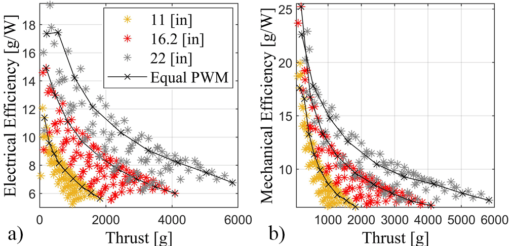
As expected, for a coaxial system, the relationship between thrust and mechanical and electrical efficiencies is not one to one, and the result is not a clear curve. Instead, the result is an area (see Fig. 1). However, the more interesting observation is that the area formed by plotting mechanical or electrical efficiency against thrust has a clear upper boundary covering the whole thrust range for the coaxial system. This indicates that every thrust along this range has a correspondent operating point on the maximum efficiency boundary. Moreover, when highlighting the points corresponding to equal commands sent to both rotors, the curve it forms is below the curve formed by the upper boundary. This is observed for most of the system's thrust range and for both mechanical and electrical efficiencies. Furthermore, the same is true not only for the results shown in Fig. 1 but for all of the experiments considered here. Therefore, based on the experiments presented, we can summarize two main observations: i) for a coaxial system comprising equal, counter-rotating electric rotors with propellers of fixed pitch, powered with the same source, there is a boundary of maximum efficiency that covers the whole thrust range and ii) the condition of equal commands for both rotors is below the maximum efficiency boundary for most of the system thrust range.
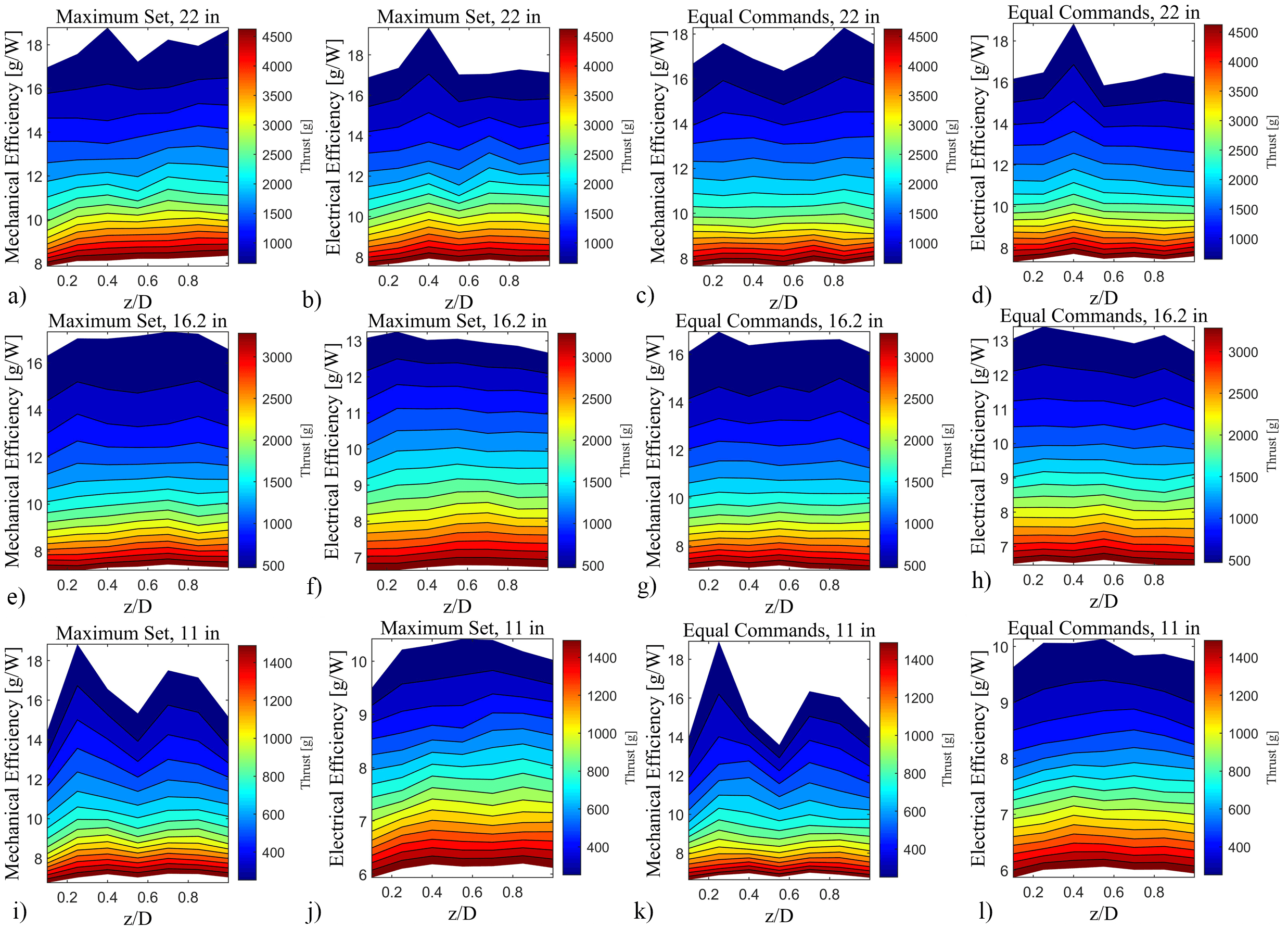
Given the observations above, the next step is to investigate how the two relevant conditions behave with the change in rotor distance. Fig. 2 displays how the efficiencies and thrust change with respect to rotor separation distances for the condition of equal commands and the observed set of data points comprising the maximum efficiency boundary. The three sets of rotors produced different behaviors. Most notable, the 11 inches rotor displays considerable change across the rotor separation range, especially for mechanical efficiency. As shown in Fig. 2. i) and k), the change is clear for both the maximum set and equal commands, and is characterized by four distinct regions: 1) a region of low efficiency at the smaller separation of z/D = 0.1, where the efficiency increases with the separation, reaching a local maximum in between 0.25 < z/D < 0.4; 2) the efficiency decreases with larger separations, going from a local maximum to a local minimum that happens at about z/D = 0.55; 3) efficiency starts to increase again with rotor separation, reaching another local maximum at around 0.7 < z/D < 0.85; and finally 4) efficiency decreases with increasing rotor separation, until the last separation ratio tested of z/D = 1. Despite still being present, the effect is much less pronounced for the electrical efficiency results, in Fig. 2 j) and l). Nonetheless, the behavior described seems to be magnified for larger efficiencies, both electrical and mechanical. The 22 inches rotor set displays similar characteristics to the 11 inches set, albeit with less pronounced efficiency variations. Moreover, such a pattern of variations is only noticeable for the maximum efficiency set, Fig. 2 a) and b). For the 22 inches rotors, besides the relatively smaller efficiency variations compared to the 11 inches results, the two local maximums also seem to be closer together and not at all present for some thrust levels. Meanwhile, the latter situation is the case for most of the results from the 16.2 inches rotors tests. The existence of two local maximums is only apparent for some low thrust levels in the mechanical efficiency measurements of both conditions, in Fig. 2 e) and g). Besides the prior observations, there are other isolated variations in the data, such as the peak in electrical efficiency for the 22 inches rotor set at z/D = 0.4. Such anomalies could be experimental errors, however, it is hard to confirm given that similar results have been obtained by other studies.
Discussions
Become a Hackaday.io Member
Create an account to leave a comment. Already have an account? Log In.