 Open Green Energy
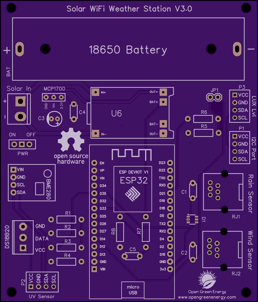
I have drawn the schematic by using EasyEDA online software after that switched to PCB layout.
All of the components you added in the schematic should be there, stacked on top of each other, ready to be placed and routed. Drag the components by grabbing on its pads. Then place it inside the rectangular borderline.
Arrange all the components in such a way that the board occupies minimum space. The smaller the board size, the cheaper will be the PCB manufacturing cost. It will be useful if this board has some mounting holes on it so that it can be mounted in an enclosure.
Now you have to route. Routing is the most fun part of this entire process. It’s like solving a puzzle! Using the tracking tool we need to connect all the components. You can use both the top and the bottom layer for avoiding overlap between two different tracks and making the tracks shorter.
You can use the Silk layer to add text to the board. Also, we are able to insert an image file, so I add an image of my website logo to be printed on the board. In the end, using the copper area tool, we need to create the ground area of the PCB. Now the PCB is ready for manufacturing.
You can order it from PCBWay
Note: When you place an order, I will get 10% donation from PCBWay for contribution to my work. Your little help may encourage me to do more awesome work in the future. Thank you for your cooperation.
Update On 24.05.2021
Now You can order the fully assembled PCB V3.0 from PCBWay. Please note that no sensors are included in the PCB, but you will get an ESP32 dev board and a Solar panel in the package.
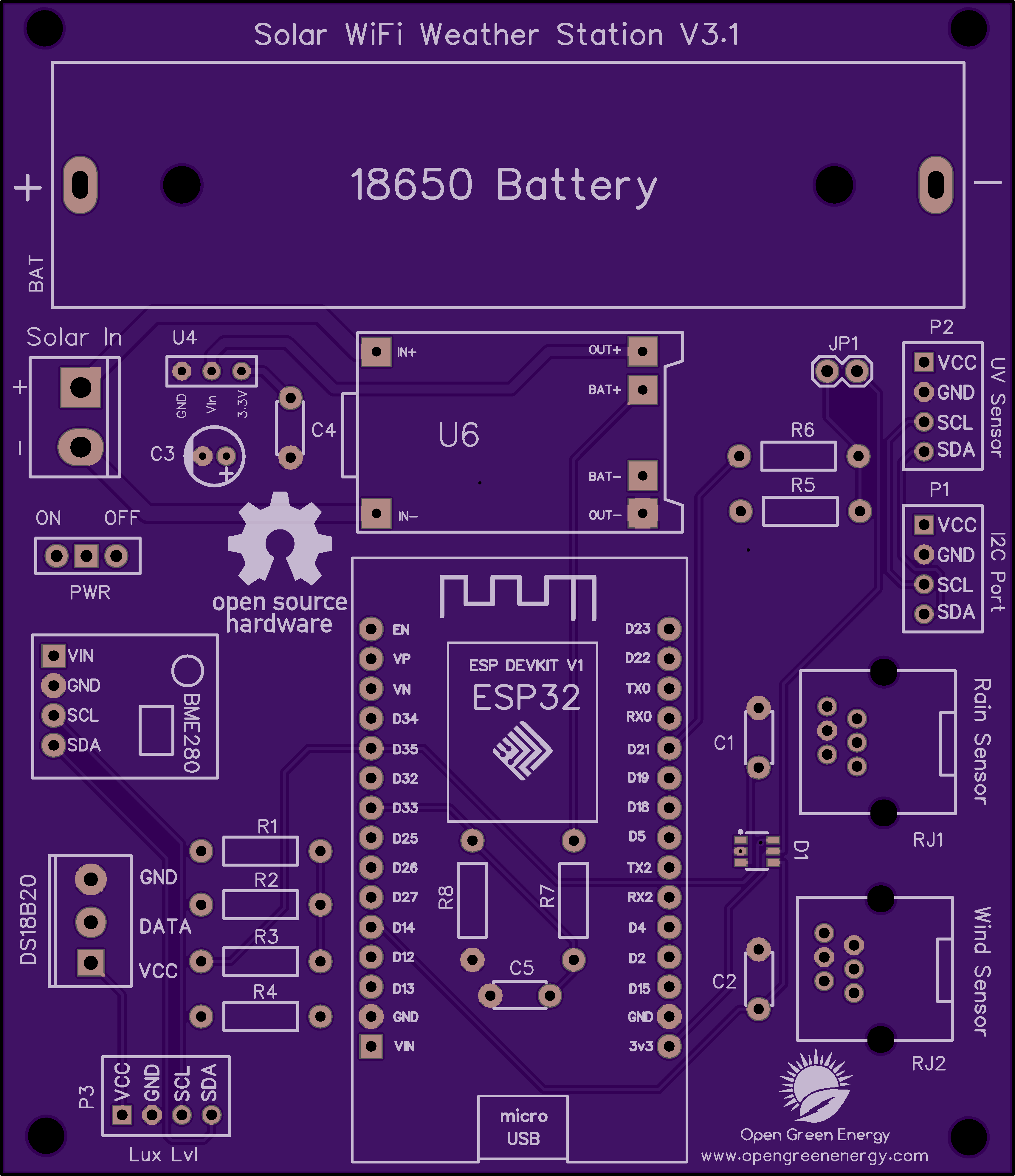
Update on 01.05.2021
The PCB V3.0 is updated to V3.1, a small change in the I2C ports ( P1, P2, and P3 ) The sequence of pins are changed from ( VCC, GND, SDA, SCL ) to ( VCC, GND, SCL, SDA ) Note: The PCB V3.0 is working perfectly, but you need extension wires to connect the sensor modules in ports P1, P2, and P3.
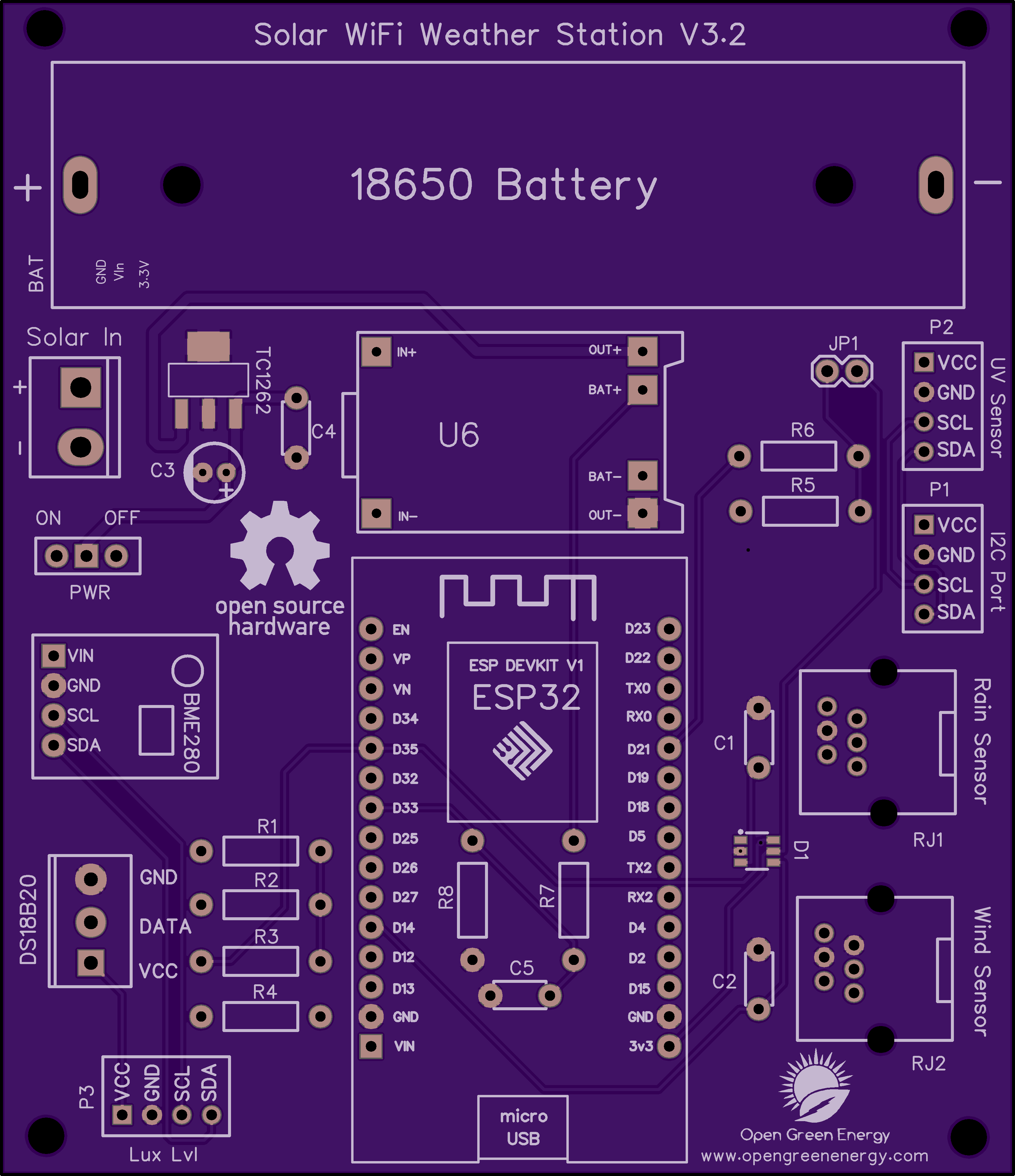
Update on 09.09.2021
The PCB V3.1 is updated to V3.2, upgrade from 200mA LDO ( MCP1700 ) to 500mA LDO ( TC1262-3.3V ) to make the power supply more stable. You can download the Gerber files or buy the PCB V3.2 from PCBWay
You can download the earlier Gerber files for PCB V3.0 and V3.1 from PCBWay.
Discussions
Become a Hackaday.io Member
Create an account to leave a comment. Already have an account? Log In.