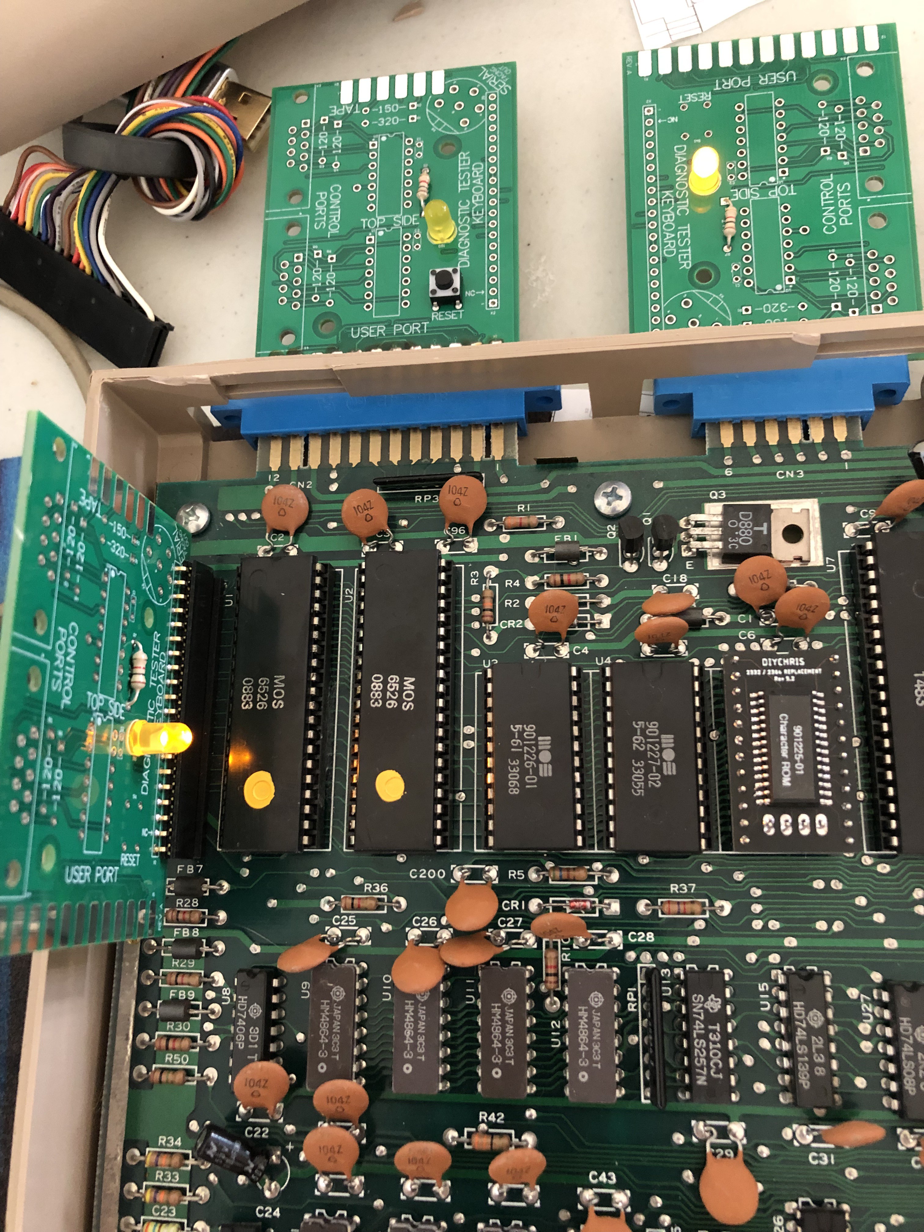
The C64 has five ports to test:
- User port
- Cassette port
- Serial port
- Control ports (2)
- Keyboard port
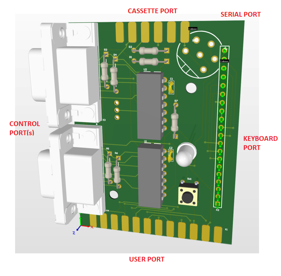
There two control ports, but I'm going to count this as one since they are right next to each other.
The keyboard port, user port, and serial port just requires simple loop back wires. The cassette port has two resistors. The control ports are a little more complicated. They have two resistors for each of the two ports. But the joystick pins feed through 4066 analog switches. And the switches are controlled by the WRITE pin on the cassette port. One wire is required to go from the cassette port to the control port.
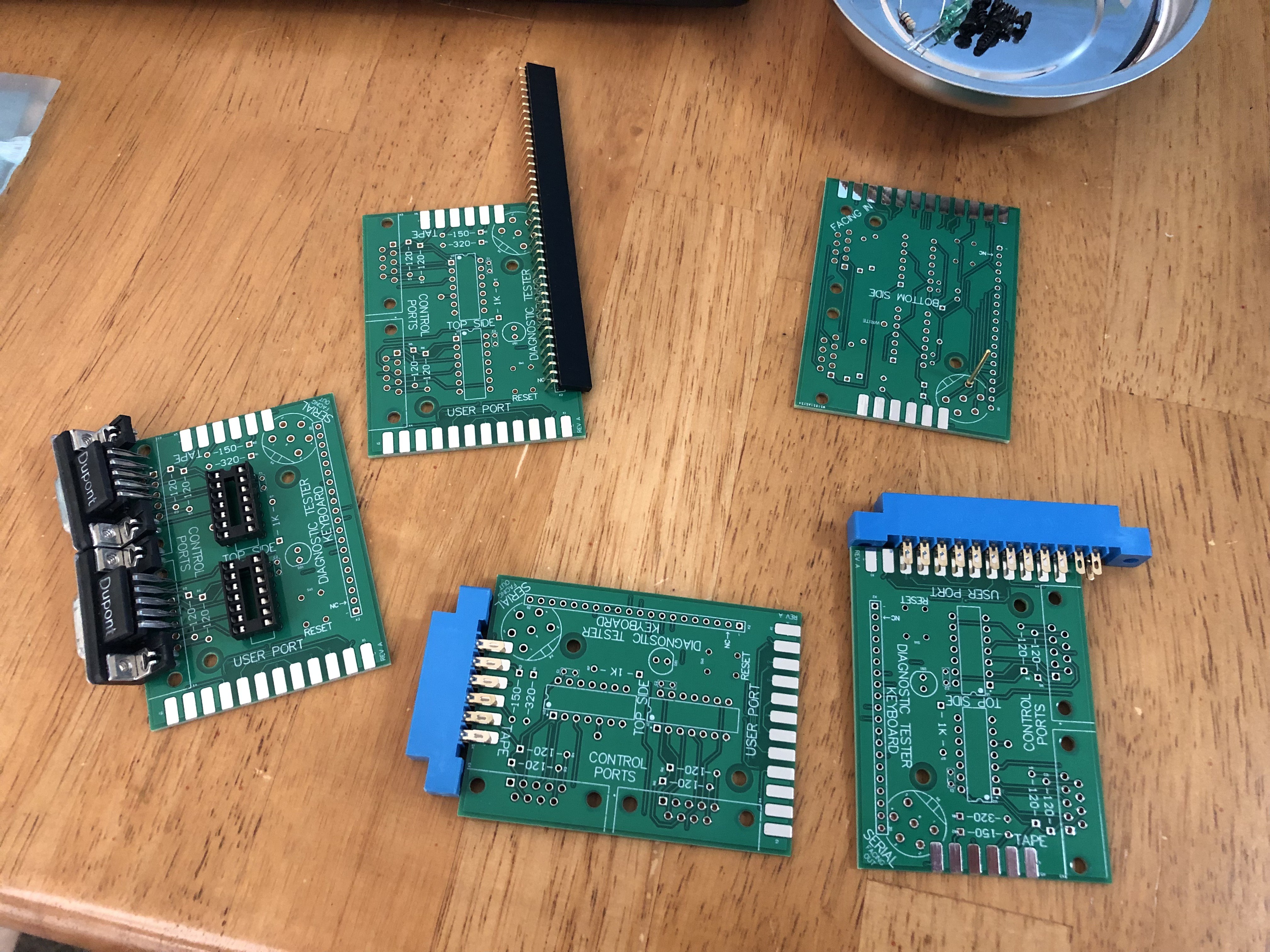
Some designs have all the logic on one board with cables running from every other port. Some designs have a separate PCB for each port. I was originally going to order this. There's shared files on PCBWay for $5 each. You'll get 5 of each board and you'll need 4 different designs. And you can't get the serial port adapter from them. So that's $20 worth of boards and you'll get 5 times as many as you need.
Since minimum quantity is 5, how about I design one board with 5 different assembly options. Then it's just $5 and I get 5 boards - just right!
There's a few other configurations - the C128 requires a different keyboard connector. Also, this doesn't include the cartridge PCB to put the software ROM on. But I don't really mind getting a few extra PCBs for cartridges. I can use 5 cartridge PCBs.
 Plasmode
 The Big One
 Bruce Land
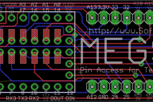
 T. B. Trzepacz