Close
0%
0%

Modular MIDI

Using a CAN bus to distribute MIDI messages in a modular synthesizer

Similar projects worth following
Modular MIDI (M2IDI) is a prototype for a bus connection to distribute MIDI messages in modular systems like eurorack.

This is a prototype MIDI transport with support for MIDI 2.0. These specifications may not be final.

M2IDI bus overview

This project contains:

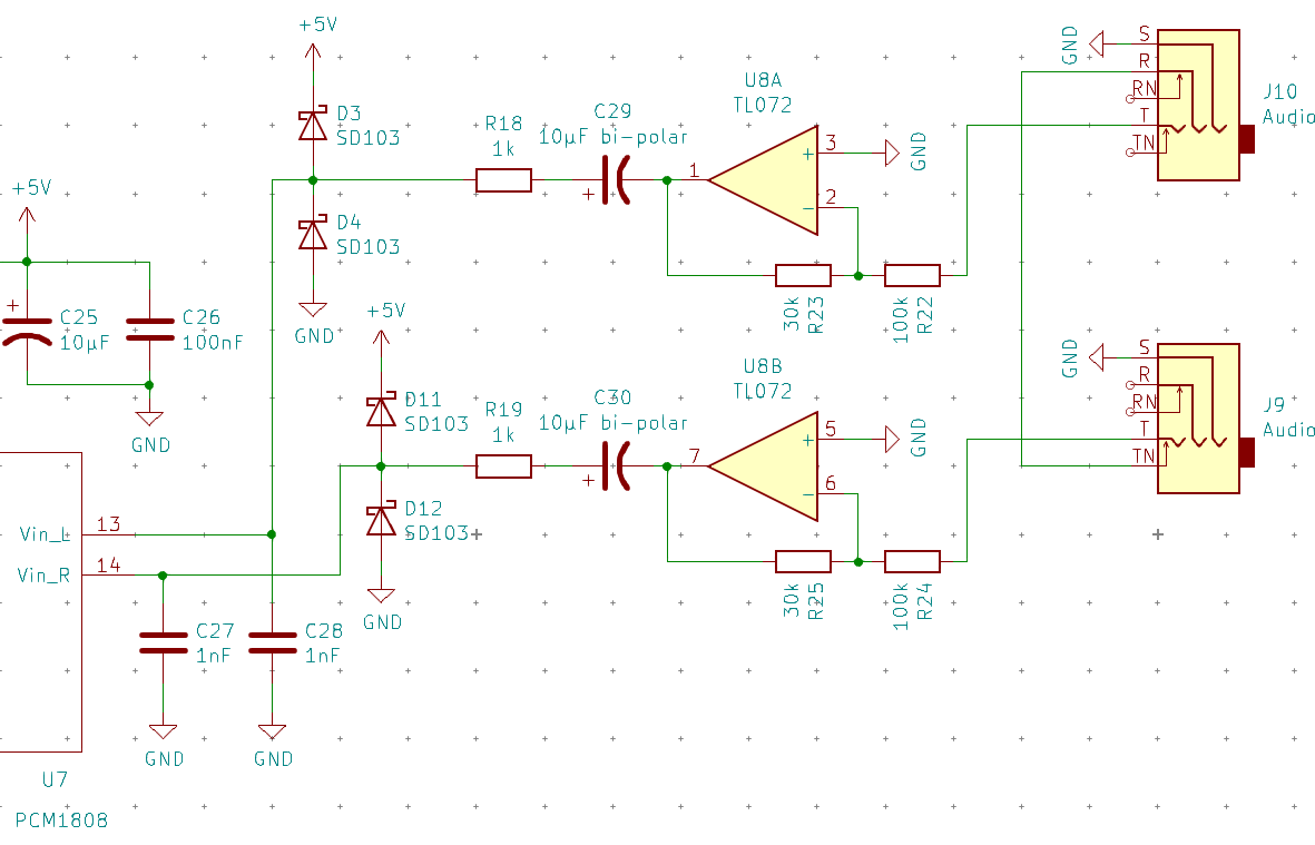
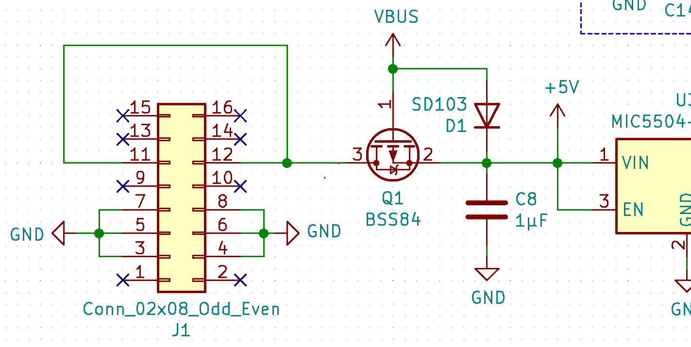
USB module - Currently not complete. Will act as a USB host or device. In device mode it transfers MIDI messages between the CAN bus and USB, and will also provide stereo audio in and out over USB. In host mode it will only connect to MIDI devices.

DIN module - Is feature complete. Transfers MIDI messages between the CAN bus and the old DIN transport.

Tangle module - Is feature complete (missing some MIDI 2.0 features). Is an analog multiplexer with 8 inputs and 8 outputs which can save mappings to MIDI program change messages.

CV16 module - Currently not complete. Has 16 general purpose analog outputs.
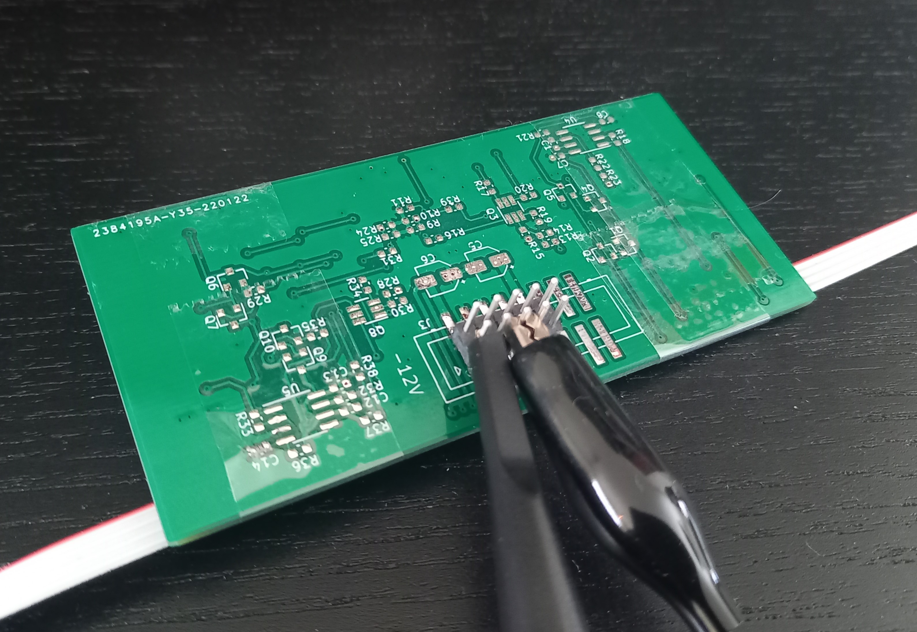
Hardware specs:

  • 4-wire flat ribbon-cable
  • MicroMatch or WR-MM connector
  • Outermost pins of the connector are connected to an RC filter to reduce EMI/EMR
  • Selectable end-termination on every module
  • CAN FD controller and transceiver

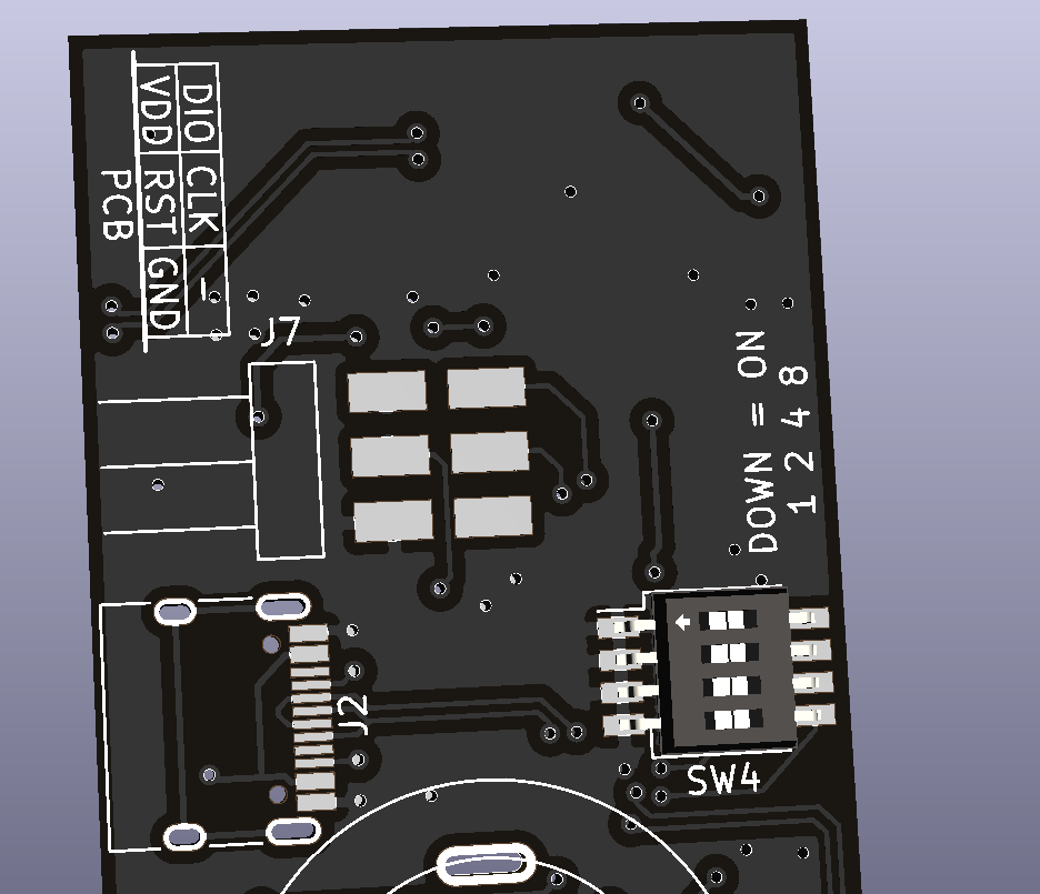
End termination can be enabled on a module with a DPDT switch, or with jumpers. And the terminated position should be clearly marked on the PCB. Split termination is preferred to minimize EMR.

M2IDI Pinout

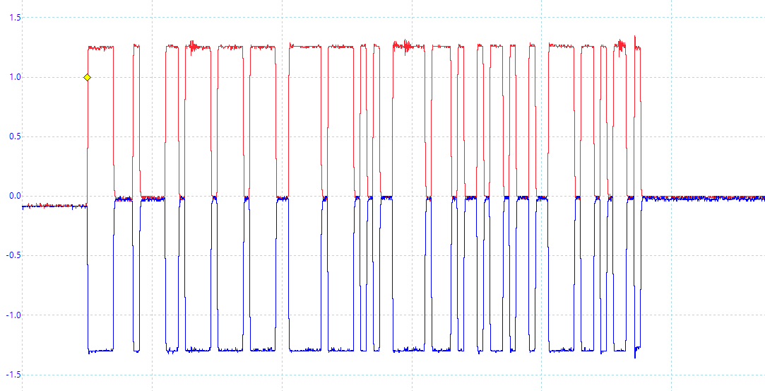
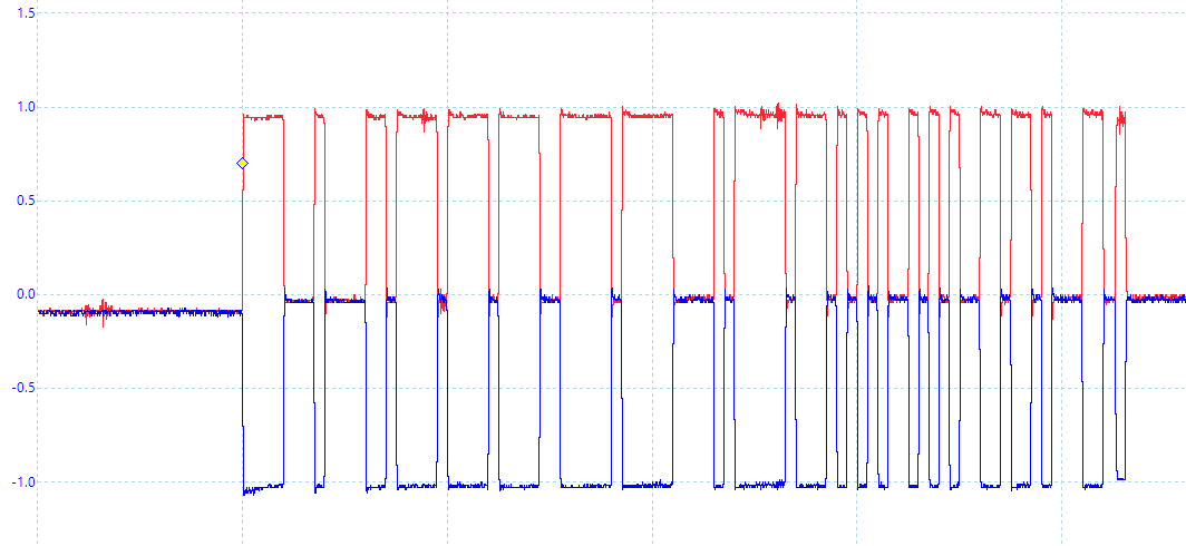
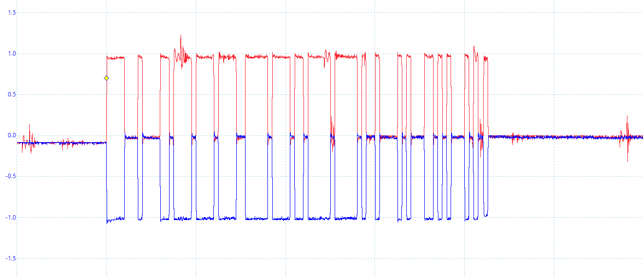
Communication specs:

  • Nominal bus speed is 1Mbps: TSEG1 = 700ns, TSEG2 = 200ns, Sync = 100ns.
  • Data bus speed can be 4Mbps: TSEG1 = 100ns, TSEG2 = 100ns, Sync = 50ns.
  • Payloads over 8 bytes should use the datarate switch, this is optional for smaller payloads.
  • 11-bit standard ID where the 4 MSb are the MIDI message type, the remaining bits should be an ID unique for every device on the bus.
  • MIDI messages are sent over the bus using the UMP format
  • Large sysex messages can transmit multiple MIDI packets in the same CAN frame, up to 64 byte.

The ID field of the CAN frame contains the ID of the transmitting device for arbitration purposes. These IDs should be randomly generated. Also, the device should generate a new ID if it receives a frame with its own ID.

CV16_LED_divider-Part.stl

A divider for the CV16 led matrix to prevent bleed between the pixels

Standard Tesselated Geometry - 217.07 kB - 10/22/2021 at 12:52

Download

  • Finishing the Tangle module

    David03/25/2024 at 18:06 0 comments

    The work on the tangle module started with a bang. Something short-circuited on the -12V rail, which blew out my mini-PSU. It turns out the reverse polarity protection had failed, the gate terminal of the MOSFET shorted with the source. I replaced it with a beefier MOSFET and it is working now, so I assume it was underdimensioned. I also forgot to connect the CAN controller interrupt pin, but is any prototype complete without any bodging?

    The bodged connection

    The light pipes are working well, there is a small gap which I think is the source of some light bleed but I can live with it. The circuit is a bit overcomplicated though, because the peak detectors are not making a difference. With audio-rate signals, the color indicates the duty cycle of the signal with yellow being roughly 50%.

    Light pipes

    As for the code I have now implemented the EEPROM driver. For a while, I wondered how to organize the data. The configuration takes up three bytes, but the MIDI bank, channel, and program number would take another four. The main problem would be finding the correct configuration because there's not enough RAM to store an index of every stored config. In the end, I stored just the three-byte configs in a main section then the bank and channel in a header section. This gives enough space to store twenty full banks by using the memory location to determine which program number is where. Having 2500 configurations across 20 banks is probably plenty, maybe even overkill.

    I also switched to the midi library from midi2.dev. It caused some weird compilation error when the library was included where the ROM overflowed by more than twice the total size. Switching to the nano GCC instructions seems to fix this issue.

    The only thing missing now is some MIDI 2.0 features like the function block and maybe some implementation of property exchange. Next up I'm going to finish soldering the CV16 module and get started on some code.

  • USB host mode

    David02/01/2024 at 21:34 0 comments

    I have slowly been making progress on the USB module over the past months, but it has not been easy. This is my first time using the RP2040 and CMAKE so that is the source of most of these hurdles. 

    Even getting blinky working with the RP2040 took a long time. The USB bootloader worked as expected, I could upload code and verify the binary file. But when it exited the bootloader the device would be completely dead. I thought it was a problem with the crystal because it was not oscillating, so I spent some time resoldering components. But it turns out the RP2040 uses two bootloaders and the default second-stage bootloader is not compatible with the flash chip I am using. Blinky finally worked when I added the right flash settings to the board header file.

    One hardware issue I discovered on the new PCBs is that the new USB CC chip is host only... It handles CC to ID interpreting and has an integrated power switch for the connected device. BUT it does not have the pulldown resistors to advertise being a device, so it will not work for a dual-role port. I have switched it back to a TUSB321 and MIC2005 in the schematics. I will not order a PCB with this fix because I can get around the bug using a USB-A to USB-C cable, so I'll get the testing done anyway.

    The first feature I tried implementing was the USB host mode because it was the biggest feature missing in the last version. I used an existing MIDI host driver to handle the USB side of driving the devices. There was a pull request with this feature on the TinyUSB library, but it never got pulled. So this driver adds the functionality from that pull request. Host mode mostly works on this module now: It works with my MPK mini and modwave, even via a USB hub. However, it does not work with the beatstep pro and a USB-C hub with extra features like an SDCARD reader and HDMI port. There is some debugging to do there I guess.

    Then I started implementing code from the previous version. There were a couple SAMD specific commands in my libraries, and linking the libraries with CMAKE gave me so much trouble. But adapting the libraries for RP2040 was otherwise pretty simple. It is now at the point where it sends messages to other modules over the CAN bus. Device mode and I2S are still not working, and I haven't implemented the external EEPROM or RAM chips in the code yet.

    This week I found out that some great resources for MIDI 2.0 have become open-source. I will probably switch to their MIDI library because it has implemented capability inquiry and other features. There are finally tools I can test MIDI 2.0 functionality with, there is even a device driver for TinyUSB. But I want to get the two other modules working before I continue with the USB module because the non-linearity of the previous CV16 module makes it impossible to do a good demo and the tangle module is almost done.

  • Completing the DIN module

    David11/18/2023 at 18:05 0 comments

    Assembling and programming the DIN module was mostly pain-free, but I could not use the bootloader. I tried flashing the bootloader but was unable to upload the program because it got stuck when initializing the flash with the applet. I even tried recompiling the applet to make sure it had the correct memory configuration. Perhaps the SAMD21G15 doesn't have enough RAM for the bootloader. It's not a huge issue though, the MCU variants with more memory are pin-compatible and I have it working on a SAMD21G17.

    Flashing activity LEDs

    Several issues have been fixed in this module, as well as some general improvements: The output is confirmed to be working as expected now. The DIP switch to select a MIDI group has been implemented. The CAN controller now filters out message types. Randomization of the CAN ID and MUID was added. The module now translates more message types between DIN and M2IDI: realtime, MIDI 2.0 voice messages, and sysex messages.

    I have also been updating the MIDI driver during this time, to adhere to the latest UMP specification. So flex and stream messages are handled, and util messages are groupless. It should also insert the bank in program change messages when translating between MIDI 1.0 and MIDI 2.0. One thing that gave me a headache while diving into the spec is that the byte order is inconsistent. Some messages, like realtime, have the least significant byte first. Other messages, like program change, have the most significant byte first. But most of them are ambiguous, left to be decided by each transport. I ended up using most significant byte first because it seems to be the most consistent overall.

    This module is basically feature-complete now, the only thing missing may be implementing a function block for MIDI discovery. Next up is probably the USB module, since I already finished soldering it.

  • New PCBs

    David11/01/2023 at 21:41 0 comments

    I have slowly been assembling the new PCBs over the past months. I'm just about halfway through the soldering now, and have started programming some of the new features.

    The new PCBs

    New PCBs, some were partially pre-assembled

    There have been a couple of announcements around synths and MIDI lately. Tiptop Audio revealed their "ART" system which is similar to patch-able MIDI. That is a very interesting way to coordinate polyphony using multiple monophonic modules. With regular MIDI I think the best way would be to have one of the modules resend the data on different MIDI channels for each voice. Maybe I should make a converter module to connect ART and M2IDI someday.

    There was also an update to the MIDI 2.0 spec. It added something called functional blocks, which give a new way to discover capabilities and negotiate MIDI 2.0. It also added two new message types: Flex data, which lets us send a sysex message to all devices in a group, and stream messages which are used for discovery of functional blocks. The utility messages have been changed to be group-less, so all devices should receive them regardless of their group. There really is a lot of programming ahead.

  • Revised USB module

    David07/14/2023 at 21:19 0 comments

    Finally, the last module to be revised is the USB module. As with previous modules I have added bootloader and reset buttons, an SMD USB connector, EEPROM, and power rail protection.

    This module also changes the MCU to RP2040. It should be easier to implement USB host mode with this change since others already have added support for it in the library.

    There should be plenty of processing power left over for some bonus features, I don't think I will implement anything beyond the basic functionality, but maybe one day.

    I added a RAM chip and a button on the front to support delay/reverb effects and changing modes, just in case I get around to implementing this. However, since this module is only 4HP wide there's not much room for controlling the effects, so it will require some creativity or MIDI CC. This module should eventually get MIDI-CI so it can be mapped and configured with that. I spent some time wondering if it would be worth it to add on such effects as an afterthought. But if it ends up unused we can just not populate those components on the PCBs.

    The 5V rail protection

    The 5V rail protection needed to be different on this module because it can supply power to the connected USB devices. This circuit blocks power from the USB connection when the 12V rail is present, which is always there when the module is powered from the rack. When the USB power is not blocked Q5 will prevent power from being spread to other modules in the rack (which currently happens when the rack is powered-down).

    The new ADC input stage

    I changed the ADC input stage to reduce its distortion since the zener diodes added some soft-clipping within the normal range of voltages. It now uses hard clipping closer to the ADC to deal with overvoltage. I also removed the ring connection from one of the inputs, so only the left input accepts stereo audio if the other input is unused.

    The previous version of this module did not comply with the jitter limitations for USB hosts because it was running off of the internal oscillator. Therefore I made sure to use a crystal oscillator in this one.

    I could probably tweak these PCBs forever, so I'll just send them all to be manufactured now.

  • Revised CV module

    David05/19/2023 at 15:02 0 comments

    Most changes on the control voltage module were the same as in previous modules. It gets an SMD USB connector, EEPROM, power rail protection, a bootloader button, and a latching bus connector. But the remaining changes are more drastic.

    The biggest change in this module is switching the MCU for an RP2040. That's not an easy choice at this point in the project, as I already have written a lot of code. But the SAMD21 already stutters, the code could definitively be optimized, but it would probably limit the features that could be added. I have been trying to keep the low-level drivers separate from the higher-level programs like the menu system and the code generating the output values, so I suppose it will test the quality of my code.

    New core PCB
    The new core PCB with the RP2040

    The pico is more popular, so it may make a more appealing open-source project. Plus it has better support in libraries like TinyUSB. People have been implementing USB MIDI host support for the RP2040 in that library, so that's less work I would need to do on the USB module.

    I also added a quad 16-bit DAC to replace the filtered PWM used in the current version of this module. This was primarily to reduce the noise on the outputs while providing better resolution. A side-effect of the change is that the outputs can be a lot faster, so the DAC could potentially provide audio-rate signals to all outputs. Seeing how far it can be pushed will be interesting.

  • Revised Multiplexer module

    David04/19/2023 at 19:50 0 comments

    Next up is the multiplexer module's revision, there are no drastic changes on this one either. Like the DIN module, this gets an SMD USB connector, 5V rail protection, a latching bus connector, and bootloader buttons.

    I also added reverse voltage protection on the +-12V rails. It shouldn't be necessary since I'm using shrouded power connectors, but it's an open-source project so people may change the components when re-creating it.

    Something I discovered with this module was that unconnected inputs caused crossover noise, so signals would appear on other inputs. I fixed this by soldering the connector's tip switch to ground so the wires are grounded when no jack is present. This has now been added to the PCB.

    I added an external EEPROM which means the routings and settings finally can be saved between power cycles. Not needing to re-configure the module every time will make it much more convenient to use.

    This module was using every available pin on the MCU (even the SWDIO pin was used for a LED), and I needed some pins for the buttons and EEPROM. So I needed to add shift-registers to control the MUX selection. This reduced the number of pins needed to control the MUXes from 24 to 3.

    Output LED circuit
    The LED control circuit for the bi-color LEDs

    The bi-color LEDs were changed from a 2-pin to a 4-pin version so both colors can shine simultaneously. This should have a better effect for audio-rate signals. The LEDs should now be green for positive signals, red for negative, and yellow for audio rate (becoming brighter with higher frequencies). This is implemented with a peak-detector circuit for each LED. The opamp can't drive high capacitive loads though, as anything over 100pF may reduce the slew rate or cause instability. Therefore the capacitor is discharged via a transistor to amplify the current. This means the discharge time depends on the gain of the transistor. Using transistors also lowers the voltage needed to drive the LEDs, so the dead zone where neither LED shines will be smaller. I could not find a THT version of these LEDs, so it will use an SMD version with a light-pipe.

  • Revised DIN module

    David04/06/2023 at 10:11 0 comments

    I started this round of revisions with the simplest module: the DIN module. 

    All this time the DIN output has not been working, because it has been inverted. It happened because the first version of this module used another MCU with the ability to invert any pin function (and I misread the datasheet for the current one). It should now be fixed by adding another inverter stage.

    I have also complained about the lack of EEPROM in this MCU. But the only thing I can think of that needs changing in this module is the MIDI group, so I added a DIP switch instead. This DIP switch is piano style for side access since the faceplate of this module can't be removed.

    Buttons to enter bootloader mode have been added, one just resets the module, and the other selects prog mode (if it is held during reset). This should make uploading firmware easier. Although the SAM-BA bootloader program has too many steps in my opinion, maybe I'll try to make it easier sometime.

    I added some protection on the 5V power to prevent the USB connection from powering the rest of the rack. I had some issues with that on the USB module, but it can occur when updating the firmware over USB on this module. This is solved with a PMOS transistor which should result in a lower voltage drop than a diode would have.

    Power protection of the 5V rail, VBUS is from the USB connector

    I considered doing hardware control of the activity LEDs by using peak detectors on the UART lines. But the PCB is already tight, so I could not fit the extra components. It isn't necessary anyways, the CPU load on this module is pretty low.

    The rest of the changes are component and silkscreen changes. The USB connector has been switched to an SMD version with THT on the shield because the THT version I used before was not within the fab's capabilities, so I had to adjust it. Room has been made for a latching bus connector which may prolong how long it lasts. The SWD programming header is now horizontal so it can be accessed from the side. And I have added reminders for which pins are which.

  • Testing the bus cable

    David03/15/2023 at 17:32 0 comments

    Long time no write, life got busy for a while. Anyway, I've been taking a closer look at the CAN bus used in this system. I have earlier guesstimated the performance of the bus, and I wanted to verify that it's going to work well. The tests I have performed so far look promising from what I can tell.

    First I tested the bus with a 10m cable, a cable of that length would cover the vast majority of modular setups. A 16-pin cable was used because it was almost the same cost as a 4-pin cable, and I can use this one to make power cables later. My biggest concern with this test was reflections of signals on the bus, but to my surprise, I could not find any. The cable has a propagation time of 4.9ns/m which means the signal can make 10 roundtrips during a single transferred bit, this gives it a lot of time to settle.

     
    Initial measurement:

    The termination resistance was initially wrong due to a (mis?)calculation of the cable's impedance. It didn't look like it caused any issues, but 240 ohm is outside the ISO spec. Reducing the termination to 120 ohm reduced the signal amplitudes to +-1V which is nominal for CAN.

    120 ohm measurement:

    The measurements show some differential noise, which moved to the other probe when the ground clip was switched. So that may be ground bounce from some digital circuit, or possibly from the USB connection. This would probably not be there if the oscilloscope wasn't attached.

    Differential noise:

    Far-field emission will likely not be an issue, a 75m-100m long bus cable would be needed to form a half-wave dipole. It could still form a short dipole though, but as far as I understand it would only be an issue if one end of the bus has a high impedance. This could happen if someone forgets to connect the termination resistance, but that would be a user error, not an issue with the bus.

    The next test was measuring the near-field emissions since the cable will be in close proximity to many other modules. I was considering getting a near-field probe for this, but I wouldn't know how to interpret those results. I imagine one of the worse situations that could occur is the bus laying in parallel with a long high-impedance trace on a module. So I grabbed one of the PCBs I had from old prototypes, found a long trace (~66mm), soldered a 1 Mohm resistance to ground, and taped the bus cable along this trace.

    The test setup:

    The signals measured on this trace had an amplitude of 10mV, which would be 0.1% of a typical analog signal in eurorack. I would say that's pretty good for a worse-case scenario.

    Radiated signal:

    Moving on to the connectors, there is one important property I've overlooked: the number of mating cycles. The connectors I have are only rated for 25 mating cycles, and the springy part is on the PCB. The bus connection is not supposed to be disconnected and reconnected often, but it would still suck having to de-solder the connector if it wears out. It seems like the manufacturers are giving a low estimate though, I tried 100 cycles on a connector and don't notice a difference in its strength. I haven't found a great alternative for 4-pin IDC connectors, so I will keep using these.

    I also want to utilize more of the built-in features of the CAN controllers. These controllers have hardware filtering of message IDs, it would be a shame not using that at all. But the message ID is also used for arbitration so some of it must be random to prevent message collisions. Message type and midi group would be good candidates for filtering, but using both in the ID would let the bus support only 8 modules. I will probably put the message type in the ID field and leave the rest random. This will let a module filter out message types it doesn't use (like sysex), so the MCU won't be interrupted when they are sent over the bus.

    One of the big features of CAN FD is the flexible data rate, allowing the payload to be sent at a higher data rate to increase data bandwidth. This increased data rate must be configured...

    Read more »

  • First demo

    David11/22/2022 at 20:31 0 comments

    I have performed some debugging since the previous log, and have finally recorded a demo. The nonlinearity of the CV module makes it impossible to keep the oscillators in tune, but this is good enough for now.


    The stuck MIDI notes I mentioned in the last log were caused by lost packets in the USB module. Which happened because the USB driver uses a bulk endpoint, and the transition to the CAN bus was not buffered. I added a buffer to make sure all packets are sent to the internal bus, which improved it. I have still noticed some issues with high throughput, so that's something to investigate further.

    The I2S connection had a couple of problems, the left and right channels were constantly swapping and the sample rate was slightly wrong. I ended up fixing the sample rate by implementing a simple
    PID regulator to adjust the frequency generated by the PLL. The Tx direction regulates the rate by aiming for a set number of samples in the buffer, this lets the USB host dictate the rate of samples while still tolerating some errors. The Rx direction can't do that because the USB driver can send extra samples in a frame, so it uses a running average of the number of samples sent in a frame. The module uses the same clock for both Rx and Tx, so the Tx takes care of regulation when both are enabled. This probably won't settle completely due to jitter in the USB frames, and it still has some stutters, but it is much better.

    Trying to fix the audio channel swapping was very annoying. It seems like there only is a problem when the DMA stops, so regulating the sample rate helps during normal operation. It can still encounter fetch errors or stop when the audio stream is turned off. The current solution is to check the word select signal when a DMA block is completed and suspend it if it's wrong. Then restart it on the next positive edge. This solution is not perfect but seems to self-correct most of the time.

    A new revision of the PCBs is getting near now, then I can finally fix the hardware issues. But before that, I want to look closer at the CAN bus.

View all 21 project logs

Enjoy this project?

Share

Discussions

Similar Projects

Does this project spark your interest?

Become a member to follow this project and never miss any updates