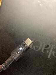
So I purchased this charger on Amazon and it came a few days ago. However, I realized it's not grounded, even though there is a ground pin. What happened?
Anyway, let's just crack it open.
Unlike the Apple 5W charger however, I don't want to destroy it. Luckily it's not too difficult to crack this open, as some prying is all that's needed to open up the two sides. Then slide everything out and you have it!
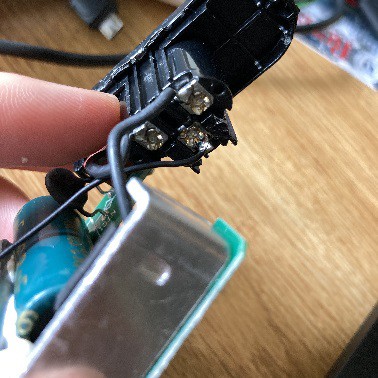
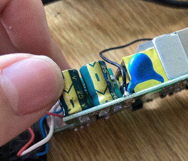
Apparently for some reason the ground pin is not connected to anything. Interesting ...
So where should it connect to? It should connect to SGND but apparently that's not it SHOULD be done, right?
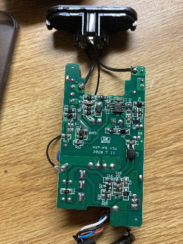
and this perhaps is what this solder pad next to the filter cap is. I mean, the other end is literally connected to this trace which is also connected to red wire (which is probably VCC), so this end is definitely NOT VCC. Then it must be GND. Let's go!
(second thought: It's not some terrible reasoning. After all, there should be three large solder pads on a single-phase PSU that is not DC -- the Live, the Neutral, and the Ground.
Let's find my tiny USB soldering iron, some solder and some wire!
...
Where is my solder?
...
ok. Guess we will have to do this without flux.
Let's just ... use this wire I have here, since one of the ends have a large clump of solder. This end will go to the AC jack. And this end let's cut it shorter and trim it, and ...
Well obviously the bare front won't do, so let's just try to get it attached here ...
(fighting with oxidizing solder while desperately trying to get the wire to coat)
well, at least we have more than one strand of copper (tin-coated-copper) physically connected to this solder ball. It's not a good solder but it should hold! Long enough for me to play some World of Tanks, at least.
(attempt to find a place for it)
Well, you have to realize that I am not putting the case back right now because with that wire attached this way, it's only a matter of time before it shook lose and short some connection.
So let's just put it on this poorly lit shelf right here. At least it's above me, and filled with unimportant stuff so I'm not going to touch it. I do NOT want to touch something with 110V AC and 300V DC flowing right next to each other.
But does it work?
.. okay. I'm not going to watch it explode in my face. So I'm going to unplug this lamp, plug this into the lamp and plug the lamp 3m away, so if this charger explodes my face wont be covered in debris.
Alright. For the moment of truth. (plugs lamp in)
(unceremoniously) yay. no explosion heard. and yes, the power led turned on.
(plugs laptop in and play world of tanks)
(does errands)
(next day)
Well, I'm going to go buy some solder so we can solder it properly and put it back together so it don't have to look like a bomb.
(went to store, purchased soldering tin and come back)
Look at that! What a beautiful solder. Even if the wire didn't went through that hole.
...
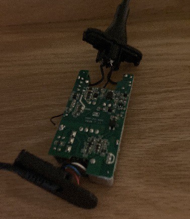
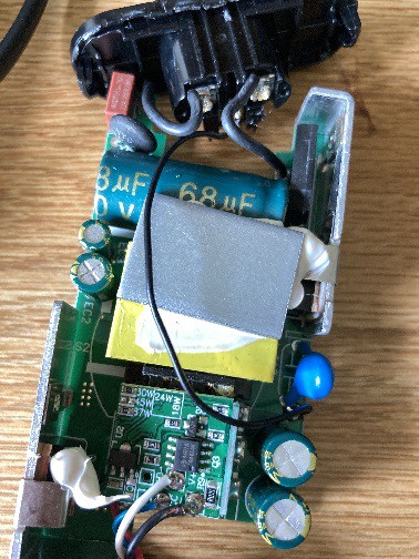
This will probably have to go this way, because this side is the switcher transistor and I don't want to get shocked. Let's route it around the transformer and down there .. right.
Let's slide everything back in .... oh it's the wrong way. Oops.
and there we go! Grounded 45W AC adapter. Why is the wire absent? Cost saving? possible ruining of ... ?
Let's just call it a manufacturing defect. I fixed a manufacturing defect. Dell product design is still impeccable as always.
If you want to read why am I doing this, read along.
_____
_____
_____
Notion:
It's common for people to call the power adapters "brick", "wart", "charger", among many other things. I will refer to them as PSU (power supply unit) here.
"ground" refer to the ground pin on the wall (that is grounded), the ground pin on the AC side. SGND refer to the ground pin on DC.
VCC refer to voltage out for the power adapters.
It's unsurprising to see why people say that you don't NEED a grounded power supply. Allow me to explain. First we will go over how does a PSU work.
Most power supplies (especially psu with variable voltage outputs) are what we call a "switching power unit". It work this way:
First, the AC is rectified through a diode bridge to become DC.
It's important to note here that it's a diode bridge, which is 4 diode, instead of one diode. Very cheap low quality PSUs have a single diode that, only give you half of the AC phase (since the other phase is technically negative), which .. well, is low quality.
Now this high voltage DC go to the "chopper" or "switcher". It's some transistors that rapidly switch this high voltage DC on and off (called Pulse Width Modulation).
This high-voltage intermittent DC goes to the flyback transformer. Because this DC is now "chopped" or discontinuous, it act like AC and thus allow the flyback transformer to convert it to low voltage AC.
Then this low voltage AC is rectified, filtered and sent through the USB-C connector.
While this is happening, several other things are going on:
A circuit on the low voltage AC side monitors the voltage and controls the switching frequency of the switcher. The signal is (preferably) sent over via a Optocoupler, which uses LED (and photodiode) to transmit signal, isolating potential high voltage in case of a catastrophic failure.
This same circuit also communicate with the device over USB-C to ask for the power specifications (how much voltage to supply on the rail). If the device did not communicate (such as a simple wireless headphone), the charger default to 5V.
If you are one of those technical guy, I can conveniently grab a random circuit diagram of a switching PSU. We will have a laptop one (somehow ungrounded) and a desktop one.
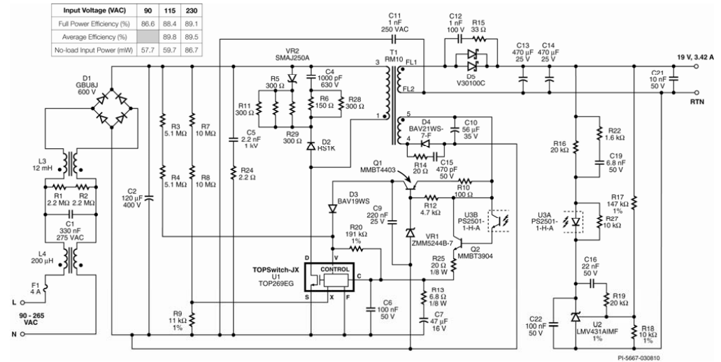
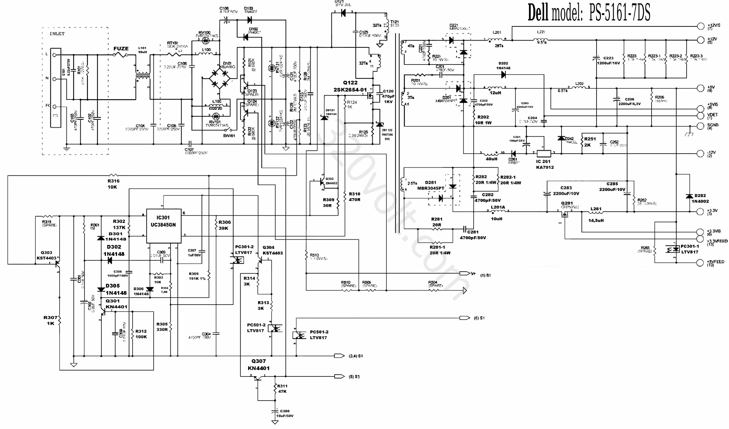
The desktop sheet is "obscurely grounded" -- the SGND is connected to "case", which is connected to ground.
*note: because datasheet of actual products are likely secret (obviously manufacturer dont want you to just go out and make clones of products), these diagrams are never official. However they are a very good rough understanding of what they actually contain (since they all operate on the switching principle)
So from all this, we can draw two conclusion:
The DC side is not electrically connected to the AC side in any case. Optocoupler is used for signal, and the power is supplied via the transformer (which have separate windings)
And because the DC side is not electrically connected to anything, there is no reference "0V" or "ground" -- there is only the 20V (or 15/9/12/5V) potential difference between the "positive" and the "negative".
Let me show you (graphically) what this means. But first, let's go over my setup:
I measured the difference between the GND on my laptop (which is connected to ground using a good three-prong charger) and GND on other charger.
I was using the ADALM1K board, a USB oscilloscope/function generator. A slight note, is that the M1K have reverse polarity protection and thus clamps out the negative phase(s).
Here are the results:
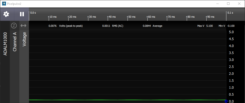
Unconnected (floating random voltage noise)
HP L25296-002 45W (weakly grounded, through a resistor)

Dell LA45NM131 45W (strongly grounded) (benchmark)

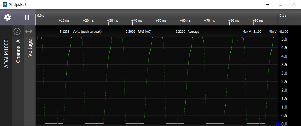
Dell DA45NM170 45W (not grounded)
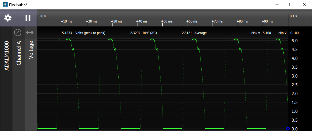
Dell DA45NM170 45W (modified, strongly grounded)

Lenovo ADLX65YLC2D 65W (not grounded)
Apple A1357 10W (strongly grounded)

Before anything, let's talk about the result from the hp one.
How am I able to verify that the HP brick is grounded through a resistor? Well, if we already know that the only way to ground a switching PSU is to physically connect the ground pin with GND (because the power pins are at 110V-240V AC), we can test the resistance between the ground pin and SGND.
So I measure the resistance between the two. It's 1 mega ohms.
Quite expectedly, none of the two power pins reads anything.
So let's go back to the question: why ground it?
Well because as you can see, the DC side is not electrically connect to mains voltage (for safety reasons), there is no reference "0V". This is the reason SGND will "float".
However, if we analyze it a bit further, having a floating SGND does not mean that the relative voltage difference between the two poles will be different -- 19V is still 19V, it's just composed of probably +10V and -9V.
However, this also means that the device (and you, the one using the device) can have a net static charge (positive or negative). And I don't have to explain why static charge is devastating to your device.
Plus, you can actually "feel" it -- if you have a macbook, that happen to run off a two prong PSU, plug it in. close the lid, and gently rub the back of your hand against the aluminum cover. Then unplug it. You will likely notice a "vibrating" feel when you plug it in. This is probably because of the fact that the supply is not grounded -- so let's ground it!