Close
0%
0%

Measure temperature and humidity with Ameba

DHT11 is a temperature and humidity sensor which operates at voltage 3.3V~5V.

Public Chat
Similar projects worth following
56 views
0 followers
DHT11 is a temperature and humidity sensor which operates at voltage 3.3V~5V. At room temperature, the measurable range of the humidity is 20% ~ 90%RH with ±5%RH precision, the measurable range of the temperature is 0 ~ 50℃ with ±2℃ precision. Another choice of temperature and humidity sensor is DHT22 sensor, which has better precision. Its measurable range of the humidity is 0%~100%RH with ±5%RH precision, the measurable range of the temperature is -40~125 ℃ with ±0.2℃ precision.

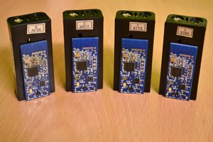
Ameba RTL8722DM is a low-power dual-band WLAN and Bluetooth Low Energy SoC by Realtek. The RTL8722DM also include memory for Wi-Fi protocol functions and application making it simple for anyone to develop various kind of IoT applications. At the same time it has a wide range of peripheral interfaces. With all these interfaces, it can connect to most of the electronics components like LEDs, temperature and humidity sensors, and so on.

More Resources:

If you need additional technical documents or the source code for this project. Please visit the official websites and join the Facebook group and forum.

  • 1 × RTL8722DM_MINI Microcontroller
  • 1 × DHT11 or DHT22 or DHT21 sensor

  • 1
    Setup

    There are 4 pins on the sensor:

    Since one of the 4 pins has no function, there are temperature/humidity sensors with only 3 pins on the market:

    DHT is normally in the sleeping mode. To get the temperature/humidity data, please follow the steps:

    1. Awake DHT: Ameba toggles low its DATA pin of GPIO. Now the DATA pin of GPIO serves as digital out to Ameba.
    2. DHT response: DHT also toggle low its DATA pin of GPIO. Now the DATA pin of GPIO serves as digital in for Ameba.
    3. DHT sends data: DHT sends out the temperature/humidity data (which has size 5 bytes) in a bit by bit manner. To represent each bit, DHT first pull low the DATA GPIO pin for a while and then pull high. If the duration of high is smaller than low, it stands for bit 0. Otherwise it stands for bit 1.

    Follow the wiring diagram below:

  • 2
    Final Result

    Open the sample code in “Files” -> “Examples” -> “AmebaGPIO” -> “DHT_Tester”. Compile and upload to Ameba, then press the reset button. The result would be shown on the Serial Monitor.

View all instructions

Enjoy this project?

Share

Discussions

Similar Projects

Does this project spark your interest?

Become a member to follow this project and never miss any updates