For a while now I've wanted to be able to control my heating from the web, or even control it with Amazon Alexa. This is my attempt at it.
Hardware overview-
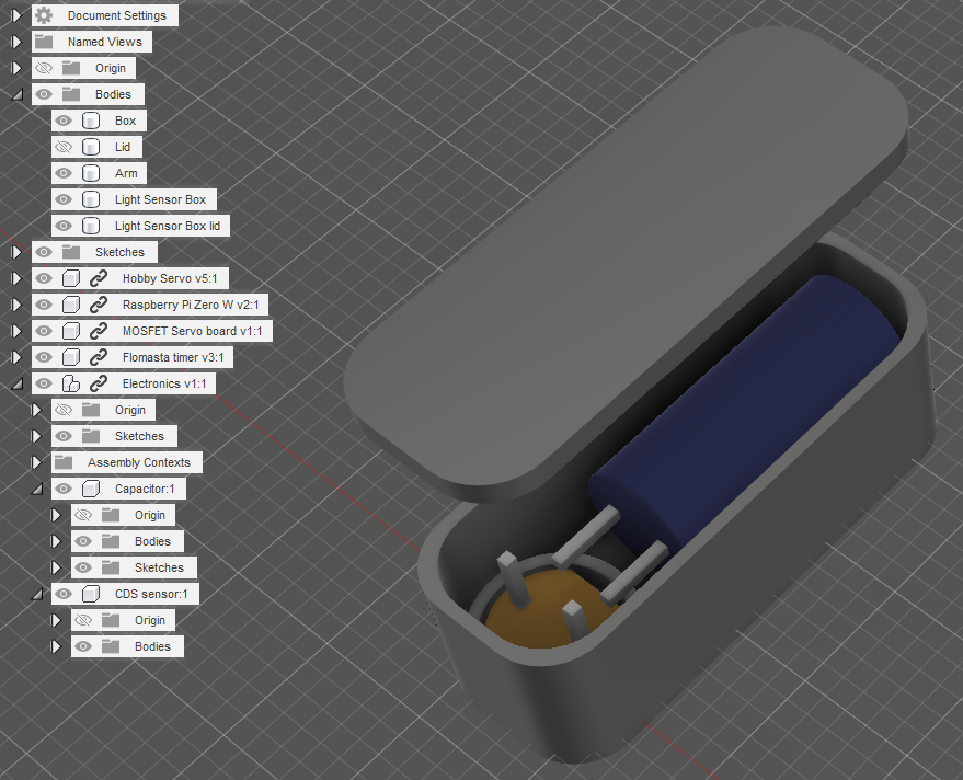
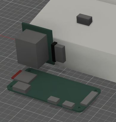
- Raspberry Pi Zero W
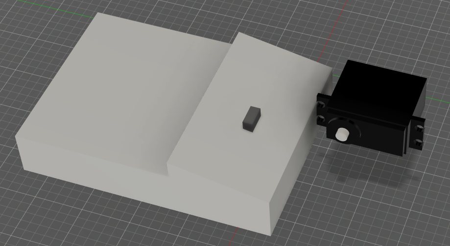
- 5v Hobby Servo motor
- Breakout board for MOSFET
Whilst the pi may be considered a bit overkill, I do want it to be 'smart' controlled, so can't make do with a PIC or Arduino. I do have a Pi Pico, but this doesn't have a network stack or supporting peripherals.
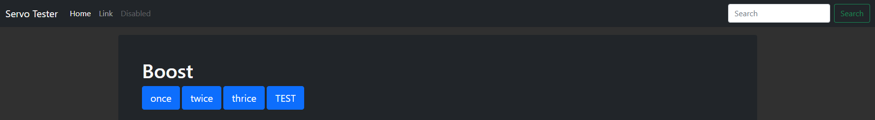
The Pi will be a normal LAMP stack device, running a small script that can be triggered to move the servo motor.
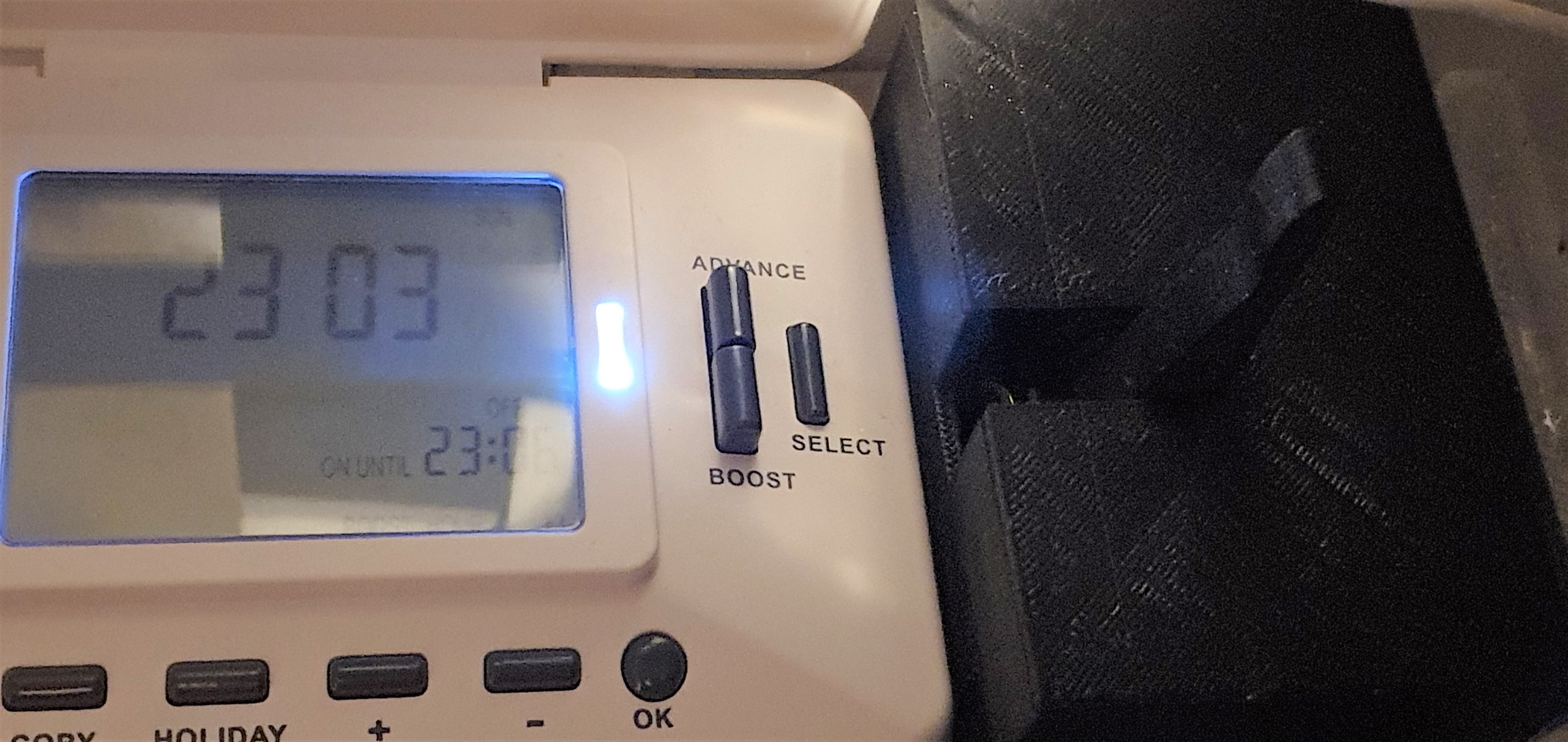
The idea being that my heating timeswitch has a BOOST button. This button works regardless of the scheduling mode the unit is in, be it on OFF mode, or on come on once, or come on twice. Boost gives you 1hr of heating, then turns off the boiler, you can press it 3 times to get 3 hours.
So I don't want to mash up and tear apart my relatively new timeswitch controller, as is usual we want to be as non-invasive as possible, and I'm definitely not up to the challenge of hooking directly into the boiler relay to turn it on - I want this timeswitch available for all other functions, eg having the heating come on on a schedule if required.
At the moment (autumn) it's that time of year I'm always turning the heating on and off (house-wide thermostats are pointless) as the outside temperature fluctuates wildly, so being able to do it without going into the boiler cupboard and fumbling around, this seems a far better proposition.
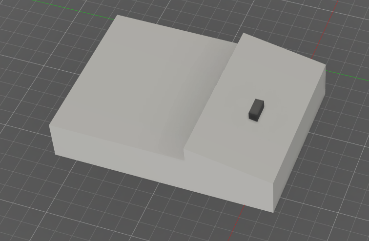
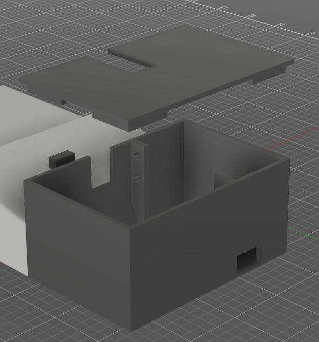
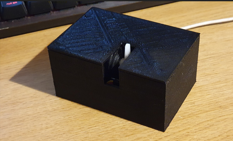
To achieve this, we'll be driving a servo motor from the Pi. The servo is positioned to be able to press the button with the swing of a servo arm. To soften any impact and prevent any switch damage occurring, I'll spring-load the end of the actuator arm.
Also I noted during experimentation that even if you tell the servo to unpower the servo arm, it still drains upwards of 50-100mA so to prevent wasted energy we'll use an N channel MOSFET to switch servo power on and off. The Pi is surprisingly low-powered, with 0.1 watt measured.
So the servo stays unpowered in it's 'home' position. When instructed, the arm will rapidly move to hover over the boost button, then slowly move down to actuate the button, immediately release, then rapid-move to the home position again. This keeps the arm well out of the way and allows me to press the buttons when I want to manually.
That's the overview covered.


 mechanicalsquid
 TeamSG
 Will Donaldson
 Smalls