Jithin Sanal
Today we are going to show you how you can make your own LED pumpkin with just a few materials. The best part? You don’t need any fancy tools or skills. All the instructions are below–get started now!

And believe it or not, these are actually PCBs. Yeah, it’s crazy but true! Let me show you what we will need and then give you the step-by-step process to make one yourself.
Everyone knows how excited we get around here when it’s time to celebrate Halloween! Lots of DIY crafts and decorating are happening. If you want an easy way to make your house or yard festive, check out this tutorial on making your very own LED pumpkin. I think they’re so cute.
DIY Halloween Pumpkin PCB Video Tutorial
In this video, we’re going to be making some cool DIY stuff for Halloween, so get ready! Today we are going to be talking about how you can create your own LED pumpkin with just a few materials.
I will be giving you complete instructions including the circuit diagram, PCB files if you want to make a PCB, and complete quotes to make one yourself.
My name is Jithin and I am super excited to teach you everything you need to know about home automation, robotics, and other fun DIY projects using Arduino and raspberry pi. If you are a true fan of all these things make sure you check out our channel. You are gonna really love it. If you want more videos like this. Make sure you subscribe to our channel by hitting the subscribe button right here.
Let’s get started.
Designing the Circuit
I used an Altium designer to draw the circuit and design the PCB. It is a powerful tool that can be used to design and create your own PCBs for your project as well as complex and multiplayer PCBs for industrial use. I will leave the link to the Altium trial version in the description. Also, there is a 30% discount if you purchase by clicking the link below. So make use of it.
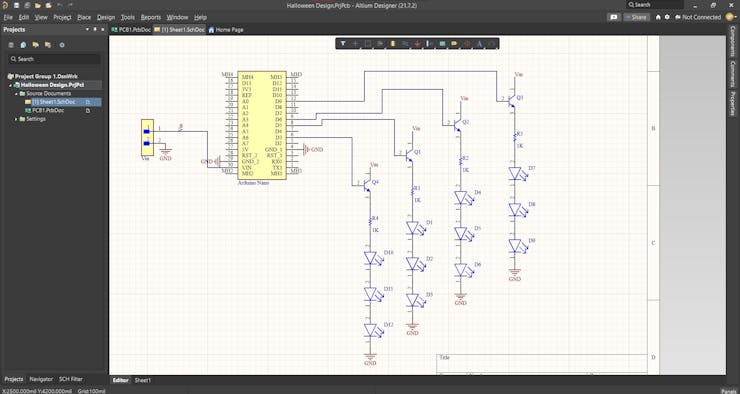
Here we are in Altium designer. Input voltage is connected to the Vin pin of Arduino. The ground pin is connected to the ground pin of Arduino.
Here we connect four transistors to four PWM pins of the Arduino, which are D3, D5, D6, and D9. And 3 LEDs are connected at the emitter pin of each transistor. The collector of the transistors is connected to the input voltage. So basically these four transistors act as switches.
The next step is where we deviate from all the previous videos. Here we will be designing a pumpkin-shaped PCB where we can securely solder the Arduino, the header pins, transistors, resistors as well as LEDs.
Designing the PCB Layout
The first thing we need is the shape of a pumpkin. For that, you can draw a pumpkin using these tools or you can import a pumpkin shape saved as a DXF file. For this project, I decided to go with the second option. I will leave the link to this DXF file in the description.
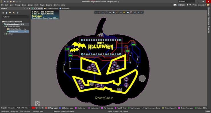
To import the pumpkin go to files import and select DXF/DWG file. Browse the file and hit open. If you want you can resize the pumpkin to fit all the components. Once the pumpkin is in the right size, we can define the boat shape using this drawing. For that go to design, board shape, and define board shape from selected objects. And there we go. The board shape has been designed. Now you can arrange all the components inside this pumpkin and once you have arranged all the components you can route it.
Getting the PCB Done
I ordered PCB from PCBWay. PCBWay is a PCB manufacturer specializing in PCB prototyping, low-volume production, and neat and tidy PCB assembly and you can create a variety of PCBs with different specifications. We will look into it in a second.

To order our PCB from PCB way, go to the PCBWay website and fill in the basic board details in the instant order form. From there we will be directed to a form where we can provide more elaborate board details. Under advanced PCBs, you can customize your PCBs.
Now update the board information in the PCB...
Read more »
 Mrinnovative

 selena1995